
下载

1
SLVUAX4–October 2016
Submit Documentation Feedback
Copyright © 2016, Texas Instruments Incorporated
TPD6S300 Evaluation Module
User's Guide
SLVUAX4–October 2016
TPD6S300 Evaluation Module
This user's guide describes the characteristics, operation, and use of the TPD6S300 evaluation module
(EVM). This EVM is a TPD6S300 integrated chip set into a USB Type-C passthrough board to allow the
user to test the operation of the TPD6S300 overvoltage protection and ESD protection in their own
system. This user's guide includes setup instructions, schematic diagrams, a bill of materials, and printed-
circuit board layout drawings for the EVM.
Contents
1 Introduction ................................................................................................................... 2
2 Board Setup .................................................................................................................. 2
2.1 Overvoltage Protection Testing ................................................................................... 2
2.2 ESD Testing......................................................................................................... 3
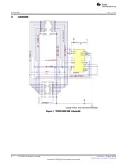
3 Schematic..................................................................................................................... 4
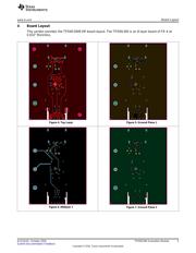
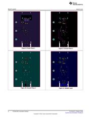
4 Board Layout ................................................................................................................. 5
5 Bill of Materials............................................................................................................... 7
List of Figures
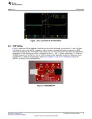
1 CC1 Line Short to 20-V Waveform........................................................................................ 3
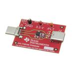
2 TPD6S300EVM .............................................................................................................. 3
3 TPD6S300EVM Schematic................................................................................................. 4
4 Top Layer .................................................................................................................... 5
5 Ground Plane 1 ............................................................................................................. 5
6 Midlayer 1..................................................................................................................... 5
7 Ground Plane 2 ............................................................................................................. 5
8 Power Plane 1................................................................................................................ 5
9 Ground Plane 3 .............................................................................................................. 5
10 Ground Plane 3 .............................................................................................................. 6
11 Bottom Layer ................................................................................................................. 6
List of Tables
1 Bill of Materials............................................................................................................... 7