


下载

Semiconductor Components Industries, LLC, 2012
April, 2012 − Rev. 4
1 Publication Order Number:
ADM1034/D
ADM1034
Thermal Monitor and Fan
Speed (RPM) Controller
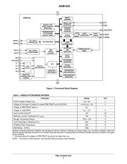
The ADM1034 is a dual-channel remote- and local-temperature
sensor and fan controller. The remote channels monitor the
temperature of two remote thermal diodes, which may be discrete
2N3904/6s or may be located on a microprocessor die. The device also
monitors its own ambient temperature.
The ADM1034 can monitor and control the speed of two cooling
fans. The user can program a target fan speed, or else use the look-up
table to input a temperature-to-fan speed profile. The look-up table
can be configured to run the fans at discrete speeds (discrete mode) or
to ramp the fan speed with temperature (linear mode).
The ADM1034 communicates over a 2-wire SMBus 2.0 interface.
An 8-level LOCATION input allows the user to choose between
SMBus 1.1 and SMBus 2.0. An ALERT
output indicates error
conditions. The THERM
I/O signals overtemperature as an output and
times THERM
assertions as an input. Pin 8 can be configured as a
reference for the THERM
(PROCHOT) input.
Features
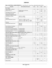
1 Local and 2 Remote Temperature Channels
1C Accuracy on Local and Remote Channels
Automatic Remote Temperature Channels, Up to 1 kW
Fast (Up to 64 Measurements per Second)
SMBus 2.0, 1.1, and 1.0 Compliant
SMBus Address Input/LOCATION Input to UDID
Programmable Over/Undertemperature Limits
Programmable Fault Queue
SMBusALERT Output
Fail-Safe Overtemperature Comparator Output
Fan Speed (RPM) Controller
Look-up Table for Temperature-to-Fan Speed Control
Linear and Discrete Options for Look-up Table
FAN_FAULT Output
THERM Input, Used to Time PROCHOT Assertions
REF Input, Used as Reference for THERM (PROCHOT)
3.0 V to 5.5 V Supply
Small 16-lead QSOP Package
This is a Pb-Free Device*
Applications
Desktop and Notebook PCs
Embedded Systems
Telecommunications Equipment
LCD Projectors
* For additional information on our Pb-Free strategy and soldering details, please
download the ON Semiconductor Soldering and Mounting Techniques
Reference Manual, SOLDERRM/D.
http://onsemi.com
See detailed ordering and shipping information in the package
dimensions section on page 37 of this data sheet.
ORDERING INFORMATION
MARKING DIAGRAM
QSOP−16
CASE 492
PIN ASSIGNMENT
(Top View)
ALERT
SCL
SDA
LOCATION
D2+
D1+
D1−
D2−
DRIVE1
TACH1
DRIVE2
TACH2
GND
V
CC
THERM
FAN_FAULT/REF
16
15
14
13
12
11
10
9
8
7
6
5
4
3
2
1
ADM1034
1034ARQZ = Specific Device Code
# = Pb-Free Package
YY = Date Code
WW = Work Week
1034A
RQZ
#YYWW
页面指南