
下载
User's Guide
SLVU986–October 2013
TPS7B6701-Q1 Evaluation Module User's Guide
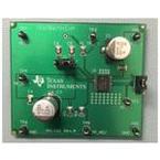
The Texas Instruments TPS7B6701EVM evaluation module (EVM) helps designers evaluate the operation
and performance of the TPS7B6701-Q1 linear regulator.
The EVM contains one linear regulator (see Table 1).
Table 1. Device and Package Configurations
Regulator IC Package
U1 TPS7B6701QPWPRQ1 PWP-20
1 Setup
This section describes the jumpers and connectors on the EVM as well and how to properly connect, set
up, and use the TPS7B6701EVM.
1.1 Input/Output Connector Descriptions
TP_VIN —This input connector is the protected power input for the regulator. The test point provides a
power (VIN) connection which powers the EVM.
J_EN —This jumper is a three-head jumper that enables and disables the device. Short pin 1 and pin 2 of
J_EN to disable the device. Short pin 2 and pin 3 of J_EN to force the voltage at EN to equal the
voltage at VIN.
TP_EN —This test point is a power test point which measures the voltage at EN. The user can also apply
power to EN through this test point directly.
TP_GND —This connector is the ground return for the regulator. Three GND test points on the EVM allow
the user to power the EVM, connect the load, and attach an oscilloscope ground lead.
TP_PG —This test point is a power test point that monitors the status of the PG pin.
J_DELAY —This jumper is a three head jumper that allows the user to select different capacitors
connected to the DELAY pin in order to vary the power-on reset delay-time.
TP_ADJ —This test point allows the user to measure the voltage of the ADJ pin.
TP_VOUT —This output connector is the power output for the regulator. The test point provides a
connection to attach a load to the EVM.
1
SLVU986–October 2013 TPS7B6701-Q1 Evaluation Module User's Guide
Submit Documentation Feedback
Copyright © 2013, Texas Instruments Incorporated