

下载
User's Guide
SLVU956A–December 2013–Revised June 2014
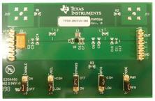
TPS6128xEVM-586 Evaluation Module
This User's Guide describes the characteristics, operation, and use of the TPS6128x evaluation module
(EVM). This EVM enables test and evaluation of Texas Instruments' TPS61281 and TPS61282 devices,
each a 2.3-MHz (typ.), up to 4.8-V, step-up dc-dc converter with integrated Pass-Through Mode. This
User's Guide includes EVM specifications, user software description, the schematic diagram, bill of
materials, and board layout. After the release of the A-version device in the summer of 2014, the EVM is
assembled with the TPS6128xA (supports PWM mode during startup which is not available for TPS6128x)
Contents
1 Introduction ................................................................................................................... 2
1.1 Requirements ....................................................................................................... 2
1.2 Applications.......................................................................................................... 2
1.3 Features.............................................................................................................. 2
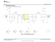
2 TPS6128xEVM Schematic ................................................................................................. 3
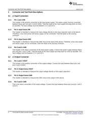
3 Connector and Test Point Descriptions................................................................................... 4
3.1 J1 Input Connectors................................................................................................ 4
3.2 J2 Output Connector ............................................................................................... 4
3.3 Other Connectors................................................................................................... 5
3.4 Jumpers.............................................................................................................. 5
4 TPS6128xEVM Assembly Drawings and Layout........................................................................ 7
5 List of Materials .............................................................................................................. 9
List of Figures
1 TPS6128xEVM-586 Schematic............................................................................................ 3
2 TPS6128xEVM-586 Component Placement ............................................................................. 7
3 TPS6128xEVM-586 Top Copper .......................................................................................... 7
4 TPS6128xEVM-586 Inner Layer 1......................................................................................... 8
5 TPS6128xEVM-586 Inner Layer 2......................................................................................... 8
6 TPS6128xEVM-586 Bottom Copper ...................................................................................... 8
1
SLVU956A–December 2013–Revised June 2014 TPS6128xEVM-586 Evaluation Module
Submit Documentation Feedback
Copyright © 2013–2014, Texas Instruments Incorporated