

下载
User's Guide
SLAU179 – April 2006
TLV320AIC29EVM and TLV320AIC29EVM-PDK
This user's guide describes the characteristics, operation, and use of the
TLV320AIC29EVM, both by itself and as part of the TLV320AIC29EVM-PDK. This
evaluation module (EVM) is a complete stereo audio codec evaluation module, with
several audio inputs and outputs, side tone, key click, and effects capabilities. A
complete circuit description, schematic diagram and bill of materials are also included.
The following related documents are available through the Texas Instruments web site
at www.ti.com .
EVM-COMPATIBLE DEVICE DATA SHEETS
DEVICE LITERATURE NUMBER
TLV320AIC29 SLAS494
TAS1020B SLES025
REG1117-5 SBVS001
TPS767D301/318 SLVS209
SN74LVC125A SCAS290
SN74LVC1G125 SCES223
SN74LVC1G07 SCES296
Contents
1 EVM Overview ............................................................................................................... 2
2 Getting Started ............................................................................................................... 2
3 Program Description ......................................................................................................... 7
4 Other board Level Connections .......................................................................................... 19
5 Physical Description ....................................................................................................... 23
List of Figures
1 Mount TLV320AIC29EVM Board on Top of USBMODEVM Board ................................................... 5
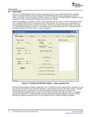
2 TLV320AIC29 EVM-PDK Software – Data Acquisition Tab ............................................................ 6
3 Data Acquisition Screen, Reading Content Box ......................................................................... 8
4 Configuration Screen ........................................................................................................ 9
5 Configuration Screen With External Reference Selection ............................................................ 10
6 Audio 1 Screen at Default ................................................................................................. 12
7 Audio 2 Screen at Default ................................................................................................. 13
8 Bass Boost Filter Screen at Default ..................................................................................... 14
9 Audio Effect Screen With Bad Data ..................................................................................... 18
10 Component Layout ......................................................................................................... 25
11 Top PCB Layer ............................................................................................................. 26
12 Power/Ground Plane 1 .................................................................................................... 27
13 Power/Ground Plane 2 .................................................................................................... 28
14 Bottom PCB Layer ......................................................................................................... 29
15 Bottom Silkscreen and Solder Mask ..................................................................................... 30
16 TSC2111EVM/TLV320AIC29EVM Schematic, Page 1 ............................................................... 31
17 TSC2111EVM/TLV320AIC29EVM Schematic, Page 2 ............................................................... 32
18 USB Board Schematic, Page 1 ........................................................................................... 33
SLAU179 – April 2006 TLV320AIC29EVM and TLV320AIC29EVM-PDK 1
Submit Documentation Feedback