


下载

© 2010-2012 Freescale Semiconductor, Inc. All rights reserved.
Document Number: AN4077
Rev. 2, 10/2012
Freescale Semiconductor
Application Note
MMA845xQ Design Checklist and
Board
Mounting Guidelines
by:
Kimberly Tuck
Applications Engineer
1.0 Introduction
This document is intended to assist customers with the
design-in of the MMA845xQ 3-axis low-g consumer grade
accelerometers. This document points out the similarities of
the pinout for these devices with a recommended layout for
implementing one board compatible for all devices. Guidelines
for board mounting to a PCB are given with recommendations
for I
2
C communication and speeds.
1.1 Key Words
Accelerometer, Board Mounting, Solder Paste, Printed Circuit
Board (PCB), I
2
C Communication, Pull-up Resistor, Pull-down
Resistor, Sensor, I/O pins, Non Solder Mask Defined, Solder
Mask, Land Pattern, Stencil, Halogen Free Package, RoHS
Compliant, Level translator, QFN, Bypass Capacitor,
MMA8450Q, MMA8451Q, MMA8452Q, MMA8453Q
TABLE OF CONTENTS
1.0 Introduction . . . . . . . . . . . . . . . . . . . . . . . . . . . . . . . . . . . . . . . . . . . . . . . . .1
1.1 Key Words . . . . . . . . . . . . . . . . . . . . . . . . . . . . . . . . . . . . . . . . . . . . . . . . . . .1
2.0 MMA845xQ Consumer 3-axis Accelerometer 3 x 3 x 1 mm . . . . . . . . . . .2
2.1 Brief Product Sensitivity and g-range Descriptions . . . . . . . . . . . . . . . . . . . . .3
2.1.1 MMA8450Q . . . . . . . . . . . . . . . . . . . . . . . . . . . . . . . . . . . . . . . . . . . . . .3
2.1.2 MMA8451Q . . . . . . . . . . . . . . . . . . . . . . . . . . . . . . . . . . . . . . . . . . . . . .3
2.1.3 MMA8452Q . . . . . . . . . . . . . . . . . . . . . . . . . . . . . . . . . . . . . . . . . . . . . .3
2.1.4 MMA8453Q Note: No HPF Data . . . . . . . . . . . . . . . . . . . . . . . . . . . . . .3
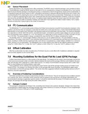
3.0 Pin Connections to the MMA845XQ . . . . . . . . . . . . . . . . . . . . . . . . . . . . . .3
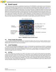
4.0 Board Layout . . . . . . . . . . . . . . . . . . . . . . . . . . . . . . . . . . . . . . . . . . . . . . . .5
4.1 Power Supply Decoupling . . . . . . . . . . . . . . . . . . . . . . . . . . . . . . . . . . . . . . . .5
4.2 Level Translators . . . . . . . . . . . . . . . . . . . . . . . . . . . . . . . . . . . . . . . . . . . . . .5
4.3 I/O Pins . . . . . . . . . . . . . . . . . . . . . . . . . . . . . . . . . . . . . . . . . . . . . . . . . . . . . .5
4.4 Sensor Placement . . . . . . . . . . . . . . . . . . . . . . . . . . . . . . . . . . . . . . . . . . . . . .6
5.0 I
2
C Communication . . . . . . . . . . . . . . . . . . . . . . . . . . . . . . . . . . . . . . . . . . .6
6.0 Offset Calibration . . . . . . . . . . . . . . . . . . . . . . . . . . . . . . . . . . . . . . . . . . . .6
7.0 Mounting Guidelines for the Quad Flat No Lead (QFN) Package . . . . . .6
7.1 Overview of Soldering Considerations . . . . . . . . . . . . . . . . . . . . . . . . . . . . . .6
7.2 Halogen Content . . . . . . . . . . . . . . . . . . . . . . . . . . . . . . . . . . . . . . . . . . . . . . .6
7.3 PCB Mounting Recommendations . . . . . . . . . . . . . . . . . . . . . . . . . . . . . . . . .7