
下载

User's Guide
SNAA048A–March 2010–Revised May 2013
AN-1680 LM49250 Evaluation Board
1 Introduction
The LM49250 evaluation board is a fully-integrated audio subsystem designed for stereo cell phone
applications. The LM49250 combines 2.5W stereo Class D speaker drivers with stereo ground referenced
headphone drivers, a class AB earpiece driver, TI 3D enhancement, volume control and input mixer into a
single device. The filterless class D amplifiers deliver 1.19W/channel into an 8 Ω load with <1% THD+N
from a 5 V supply.
The LM49250 features a new circuit technology that utilizes a charge pump to generate a negative supply
voltage. This allows the outputs to be biased about ground, thereby eliminating output-coupling capacitors
typically used with normal single-ended loads. To supply the required voltage level to the ground
referenced amplifier, an LDO has been integrated. For improved noise immunity, the LM49250 features
fully differential left, right and mono inputs. The three inputs can be mixed/multiplexed to either the
loudspeaker, headphone or earpiece amplifiers. The left and right differential inputs can be used as
separate single-ended inputs, mixing multiple stereo audio sources. The mixer, volume control, and device
mode select are controlled through an I2C compatible interface.
Output short circuit and thermal overload protection prevent the device from being damaged during fault
conditions. Superior click and pop suppression eliminates audible transients on power-up/down and during
shutdown.
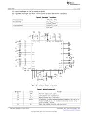
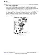
The LM49250 evaluation board (shown in Figure 1) allows the user to easily evaluate the performance
and characteristics of the LM49250 device. It provides connectors for audio inputs, audio outputs, I
2
C
control, power supply, and shutdown control.
2 Quick Start
The following procedures are needed to begin the
1. Connect a shunt across the center pin (I
2
C VDD) and the VDD pin of J9 (I
2
CVDD = VDD).
2. Connect a shunt across the center RESET pin and the “+” terminal of J4 (I2C reset pin).
3. Connect a 4Ω or 8Ω speaker across the “+” and “-” pins of J2 (left loudspeaker output) and J3 (right
loudspeaker output).
4. Connect stereo headphones to the headphone jack (U2).
5. Connect a 16Ω or 32Ω speaker across the “+” and “-” pins of J1 (earpiece output).
6. Connect a 3.6V power supply to the VDD pin of J8, and the power supply ground source to the GND
pin of J8.
7. Apply a positive audio signal source to the “+” terminals of J5 (right input), J6 (left input), and J7 (mono
input), and a negative audio signal source to the “-” terminals of J5 (right input), J6 (left input), and J7
(mono input).
8. Connect the USB interface card to a PC with the USB cable. Connect cable attached to USB interface
card to the I
2
C interface jumper (J10)on demo board.
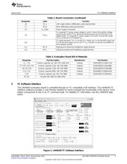
9. Open LM49250 I
2
C interface software.
10. Turn on the power supply and audio source.
11. In the LM49250 I
2
C interface software (see Figure 2) select:
• “ON” for Earpiece, Left Loudspeaker, Right Loudspeaker, Left Headphone, and Right Headphone
• Mode “2” for Loudspeaker Output Mode, Headphone Output Mode, and Earpiece Output Mode
All trademarks are the property of their respective owners.
1
SNAA048A–March 2010–Revised May 2013 AN-1680 LM49250 Evaluation Board
Submit Documentation Feedback
Copyright © 2010–2013, Texas Instruments Incorporated