

下载
User's Guide
SNVA151A–September 2006–Revised May 2013
AN-1450 LM3743 Evaluation Board
1 Introduction
The LM3743 is a voltage mode PWM buck controller that implements synchronous rectification. It provides
a low cost, fault tolerant, and efficient point of load solution. To reduce component count several
parameters are fixed, such as switching frequency and the short circuit protection level. In steady state
operation the LM3743 is always synchronous, even at no load, thus simplifying the compensation design.
The LM3743 ensures a smooth and controlled start-up when the output is pre-biased. Two levels of
current limit protection enhance the robustness of the power supply and requires no current sense resistor
in the power path. The primary level of protection is the low side current limit and is achieved by sensing
the voltage V
DS
across the low side MOSFET. The second level of protection is the high side current limit,
which protects power components from extremely high currents caused by switch node short-circuit to
ground.
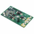
2 Specifics Of The Board
The input voltage to the power components (V
IN
) and the input voltage on the control section (V
CC
) must
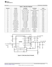
be in the range of 3.0V to 5.5V. The 300 kHz demo board design regulates to an output voltage of 1.2V
and up to 13A. The 1 MHz demo board design regulates to an output voltage of 1.5V and up to 9A. For
additional design modifications, see the Design Consideration section of the LM3743 High-Performance
Synchronous Buck Controller with Comprehensive Fault Protection Features Data Sheet (SNVS427). The
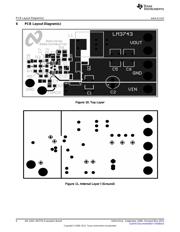
PCB is designed on four layers, the top and bottom layers are 2oz. copper and the two inner layers are
1oz. copper. The board measures 2.4 in. x 1.36 in. (6.1 cm x 3.44 cm) and is 62mil (.062”) thick on a FR4
laminate.
3 Additional Footprints
When the tracking feature of the LM3743 is used, remove the soft-start capacitor C4 and use a resistor
divider on designators R7 and C4. The ground and track post have been provided for your connecting
convenience.
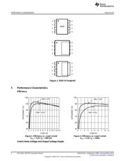
4 MOSFET Footprints
The LM3743 demo board accommodates footprints for single N-MOSFETs with standard SOIC-8
packages and with exposed drain pads. The MOSFET footprint has the pinout as shown in Figure 1.
Some examples of MOSFET packages with exposed drain pads are also illustrated.
All trademarks are the property of their respective owners.
1
SNVA151A–September 2006–Revised May 2013 AN-1450 LM3743 Evaluation Board
Submit Documentation Feedback
Copyright © 2006–2013, Texas Instruments Incorporated