


下载
1
ISL94212EVKIT1Z Evaluation Kit User Guide
Description
The ISL94212EVKIT1Z is a kit that facilitates use of the
ISL94212
BMS device. The ISL94212 monitors cell voltage and
temperature. It converts the cell voltages and temperatures to
14-bit digital values, provides cell balance control, It provides
significant fault detection. The ISL94212 can operate in a single
device configuration, or multiple kits can be cascaded using a
built-in daisy chain connection. The daisy chain hardware
provides robust, redundant board-to- board communications.
Specifications
This board has been configured and optimized for the following
operating conditions:
•V
BAT
= 6V to 60V
•V
BAT
daisy chain = 10V to 60V
•VC
n
(for n = 1 to 12) = V(VCn-1) to V(VCn-1) + 5V
•CB
n
(for n = 1 to 9) = V(VCn-1) to V(VCn-1) + 9V
•CB
n
(for n = 10 to 12) = V(VCn) -9V to V(VCn)
• External inputs Ext
1 -4
= 0V to 2.5V
• SPI communications refer to ISL94212
datasheet
•V
POR
(V
BAT
) voltage (rising) typical 5.1V
Key Features
• Supports both stand alone and daisy chained configurations
• Daisy chaining with both connector only or wire jumper
options
•GUI provided export option for generation of detailed
register and/or SPI communications log files.
• USB dongle runs HID firmware for driver-less enumeration
and communications with Windows platforms
• GUI add-in chart generation tool supports real-time
graphing, zoom and export of captured data.
• Software provides checksum requirements associated with
daisy chain communications.
• Kit includes “Battery Emulation” board(s) for cell voltages
generation.
References
ISL94212 web page
ISL94212
datasheet
Ordering Information
PART NUMBER DESCRIPTION (Note)
ISL94212EVKIT1Z ISL94212 master
ISL94212EVZ ISL94212 slave/daisy chain kit to be
used as either “middle” or “top” device(s)
NOTE: See “What is inside” on page 2
for kit details.
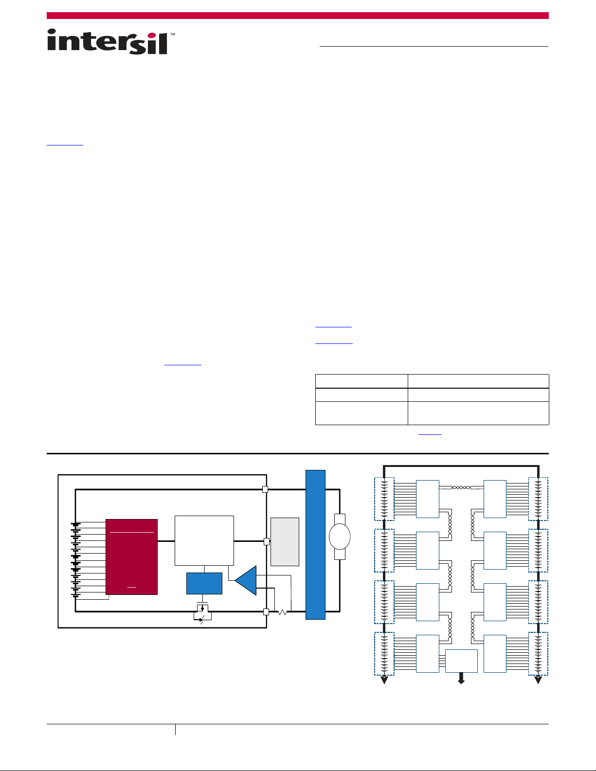
FIGURE 1. SINGLE DEVICE CONFIGURATION
FIGURE 2. DAISY CHAIN CONFIGURATION
MICROCONTROLLER
CURRENT MONITORING
COMMUNICATION
POWER FET CONTROL
PACK CAPACITY MONITOR
ANALOG FRONT END
LEVEL SHIFTING
VOLTAGE MONITOR
TEMP MONITOR
OV, OT DETECTION
OP EN WIRE DETECT
CELL BALANCING
VOLTAGE REGULATOR
ADC
SPI
FET DRIVER
CURRENT
MOTOR DRIVE ELECTRONICS
SYSTEM
ELECTRONICS
Applications requiring 12 cells or less can operate with a single device as
shown above.
Also the ISL94212 can also operate in a 2 to 14 device configuration (Daisy
Chain). See example to the right.
MONITORING
ELECTRON IC S
MONITORING
ELECTRON IC S
MONITORING
ELECTRON IC S
MONITORING
ELECTRONICS
MONITORING
ELECTRON IC S
MONITORING
ELECTRONICS
MONITORING
ELECTRON IC S
MONITORING
ELECTRONICS
MICRO-
CONTROLLER
August 26, 2015
UG048.0
User Guide 048
CAUTION: These devices are sensitive to electrostatic discharge; follow proper IC Handling Procedures.
1-888-INTERSIL or 1-888-468-3774
| Copyright Intersil Americas LLC 2015. All Rights Reserved
Intersil (and design) is a trademark owned by Intersil Corporation or one of its subsidiaries.
All other trademarks mentioned are the property of their respective owners.