

下载
QUICK START GUIDE FOR DEMONSTRATION CIRCUIT 921
MICROPOWER SYNCHRONOUS BUCK-BOOST CONVERTER
1
LTC3532
DESCRIPTION
Demonstration circuit 921 is a micropower synchro-
nous buck-boost converter based on the LTC3532
monolithic buck-boost regulator. The DC921 has an
input voltage range of 2.4 V to 5.5V and an output of
3.3V @ 300mA. The converter can work under manual
or programmable automatic burst mode, providing
high conversion efficiency over a wide range of load
currents. The LTC3532 comes in a 10 lead 3×3 DFN
package. These features make the DC921 demo board
an ideal circuit for use in Li-Ion battery-powered,
hand-held applications.
NOTE
:
Some of the optional components should be stuffed for
Vin > 4.5V as discussed in the Datasheet
.
Design files for this circuit board are available. Call
the LTC factory.
LTC is a trademark of Linear Technology Corporation
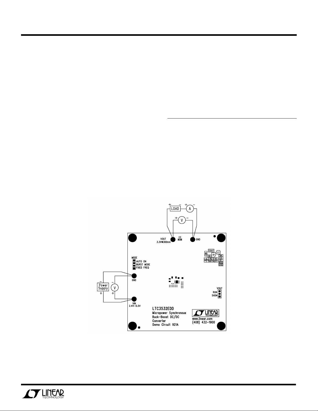
QUICK START PROCEDURE
Refer to Figure 1 for proper measurement equipment
setup and follow the procedure below:
1.
Start with Load set to 0A.
2.
Set Power Supply anywhere between 2.4V to 5.5V.
3.
The Load can be set from 0 – 300mA.
Figure 1. Proper Measurement Equipment Setup