

下载
1
dc2014af
DEMO MANUAL DC2014A
Description
LT8302
Micropower No-Opto
Isolated Flyback Converter
Demonstration circuit 2014A is a micropower No-Opto
isolated flyback converter featuring the LT
®
8302. This demo
circuit outputs 5V, and maintains tight regulation with a
load current from 10mA to 2.2A over an input voltage
from 10V to 30V. The output current capability increases
with the input voltage.
The LT8302 typically needs less than 0.5% of its full output
power as a minimum load to maintain good output voltage
regulation. On the DC2014A, in order to avoid pre-loading,
a 5.6V Zener diode is placed between its V
OUT
+
and V
OUT
–
to serve as a minimum load.
Transformer leakage inductance causes a voltage spike
on the primary side after the power switch turns off. To
limit this leakage inductance spike within MOSFET volt
-
age rating of 65V, an RC snubber and a TVS clamp are
installed to damp the ringing and clamp the MOSFET drain
voltage to a safe level.
The Performance Summary table summarizes the perfor
-
mance of the demo board at room temperature. The demo
circuit can be easily modified for different applications with
some pre-designed transformers.
L, LT, LTC, LTM, Burst Mode, Linear Technology and the Linear logo are registered trademarks
of Linear Technology Corporation. All other trademarks are the property of their respective
owners.
performance summary
The LT
®
8302 is a simple to use monolithic micropower
isolated flyback converter. By sampling the isolated output
voltage directly from the primary-side flyback waveform,
the part requires no third winding or opto-isolator for
regulation. The output voltage is programmed with two
external resistors and a third optional temperature compen
-
sation resistor. By integrating the loop compensation and
soft-start inside, the part reduces the number of external
components. Boundary mode operation provides a small
magnetic solution with excellent load regulation. Low ripple
Burst Mode
®
operation maintains high efficiency at light
load while minimizing the output voltage ripple. A 3.6A,
65V DMOS power switch is integrated along with all the
high voltage circuitry and control logic into a thermally
enhanced 8-lead SO package.
The LT8302 data sheet gives a complete description of
the part, operation and application information. The data
sheet must be read in conjunction with this quick start
guide for demo circuit 2014A.
Design files for this circuit board are available at
http://www.linear.com/demo
Specifications are at T
A
= 25°C
PARAMETER CONDITIONS MIN TYP MAX UNITS
Input Voltage 10 24 30 V
Output Voltage V
IN
= 10V to 30V, I
OUT
= 10mA to 2.2A 4.75 5 5.25 V
Maximum Output Current V
IN
> 15V 2.2 A
Output Voltage Ripple (Peak to Peak) V
IN
= 10V to 30V, I
OUT
= 2.2A 100 mV
Typical Switching Frequency V
IN
= 24V, I
OUT
= 2.2A 345 kHz
Minimum Switching Frequency I
OUT
= 0mA 12 kHz
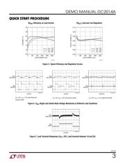
Efficiency V
IN
= 10V, I
OUT
= 2.2A
V
IN
= 24V, I
OUT
= 2.2A
V
IN
= 30V, I
OUT
= 2.2A
80
84
84
%
%
%