


下载

User's Guide
SLAU186A – August 2006 – Revised September 2008
ADS848xEVM
This user's guide describes the characteristics, operation, and use of the ADS8482 18-bit, 1-MHz, parallel
interface and ADS8484 18-bit, 1.25-MHz, parallel interface, analog-to-digital converter (ADC) evaluation
module (EVM). A complete circuit description, schematic diagram, and bill of materials are included.
Throughout this document, the term evaluation module and the abbreviation EVM are synonymous with
the ADS848xEVM. For ease of reading, this user's guide refers to the ADS8482EVM or ADS8484EVM as
the ADS848xEVM. Operation of the EVM for both devices is identical, unless otherwise noted.
Contents
1 EVM Overview ............................................................................................................... 2
2 Introduction ................................................................................................................... 2
3 Analog Interface .............................................................................................................. 2
4 Digital Interface .............................................................................................................. 6
5 Power Supplies .............................................................................................................. 8
6 Using the ADS848xEVM .................................................................................................... 9
7 Related Documentation from Texas Instruments ...................................................................... 10
Appendix A ADS848xEVM Bill of Materials .................................................................................. 11
Appendix B ADS848xEVM LAYOUT ......................................................................................... 13
Appendix C ADS848xEVM Schematic ....................................................................................... 19
List of Figures
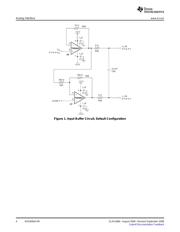
1 Input Buffer Circuit, Default Configuration ................................................................................ 4
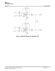
2 Input Buffer, Bipolar Fully Differential Input .............................................................................. 5
B-1 Top Layer – Layer 1 ....................................................................................................... 13
B-2 Ground Plane – Layer 2 ................................................................................................... 14
B-3 Power Plane – Layer 3 .................................................................................................... 15
B-4 Bottom Layer – Layer 4 ................................................................................................... 16
B-5 Top Overlay ................................................................................................................. 17
B-6 Bottom Overlay ............................................................................................................. 18
List of Tables
1 Analog Input Connector ..................................................................................................... 2
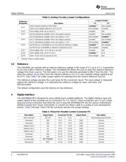
2 Analog Circuitry Jumper Configurations .................................................................................. 6
3 Pinout for Parallel Control Connector P3 ................................................................................. 6
4 Jumper Settings .............................................................................................................. 7
5 Data Bus Connector P2 ..................................................................................................... 7
6 Pinout for Converter Control Connector, J6 .............................................................................. 8
7 Power-Supply Test Points .................................................................................................. 8
8 Power Connector, J1, Pinout ............................................................................................... 8
A-1 Bill of Materials ............................................................................................................. 11
C5000, C6000 are trademarks of Texas Instruments.
All other trademarks are the property of their respective owners.
SLAU186A – August 2006 – Revised September 2008 ADS848xEVM 1
Submit Documentation Feedback