

下载

Freescale Semiconductor
Data Sheet: Technical Data
Document Number: MPC5604P
Rev. 8, 07/2012
© Freescale, Inc., 2008–2012. All rights reserved.
Freescale reserves the right to change the detail specifications as may be required to permit
improvements in the design of its products.
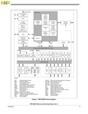
MPC5604P
144 LQFP
20 mm x 20 mm
100 LQFP
14 mm x 14 mm
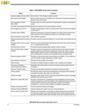
• Up to 64 MHz, single issue, 32-bit CPU core complex
(e200z0h)
— Compliant with Power Architecture embedded
category
— Variable Length Encoding (VLE)
• Memory organization
— Up to 512 KB on-chip code flash memory with ECC
and erase/program controller
— Optional 64 (4 × 16) KB on-chip data flash memory
with ECC for EEPROM emulation
— Up to 40 KB on-chip SRAM with ECC
• Fail safe protection
— Programmable watchdog timer
— Non-maskable interrupt
— Fault collection unit
• Nexus L2+ interface
• Interrupts
— 16-channel eDMA controller
— 16 priority level controller
• General purpose I/Os individually programmable as input,
output or special function
• 2 general purpose eTimer units
— 6 timers each with up/down count capabilities
— 16-bit resolution, cascadable counters
— Quadrature decode with rotation direction flag
— Double buffer input capture and output compare
• Communications interfaces
— 2 LINFlex channels (LIN 2.1)
— 4 DSPI channels with automatic chip select
generation
— 1 FlexCAN interface (2.0B Active) with 32 message
objects
— 1 safety port based on FlexCAN with 32 message
objects and up to 7.5 Mbit/s capability; usable as
second CAN when not used as safety port
— 1 FlexRay™ module (V2.1) with selectable dual or
single channel support, 32 message objects and up to
10 Mbit/s
• Two 10-bit analog-to-digital converters (ADC)
— 2 × 15 input channels, 4 channels shared between the
two ADCs
— Conversion time < 1 µs including sampling time at
full precision
— Programmable Cross Triggering Unit (CTU)
— 4 analog watchdogs with interrupt capability
• On-chip CAN/UART bootstrap loader with Boot Assist
Module (BAM)
•1 FlexPWM unit
— 8 complementary or independent outputs with ADC
synchronization signals
— Polarity control, reload unit
— Integrated configurable dead time unit and inverter
fault input pins
— 16-bit resolution, up to 2 × f
CPU
— Lockable configuration
• Clock generation
— 4–40 MHz main oscillator
— 16 MHz internal RC oscillator
— Software controlled FMPLL capable of speeds as fast
as 64 MHz
• Voltage supply
— 3.3 V or 5 V supply for I/Os and ADC
— On-chip single supply voltage regulator with external
ballast transistor
• Operating temperature ranges: –40 to 125 °C or –40
to 105 °C
Qorivva MPC5604P
Microcontroller Data Sheet
页面指南