


下载

Freescale Semiconductor Inc.
Data Sheet: Technical Data
Document Number: IMX6DQIEC
Rev. 4, 07/2015
Package Information
Case FCPBGA 21 x 21 mm, 0.8 mm pitch
Ordering Information
See Table 1 on page 2
© 2012-2015 Freescale Semiconductor, Inc. All rights reserved.
MCIMX6QxCxxxxC
MCIMX6QxCxxxxD
MCIMX6DxCxxxxC
MCIMX6DxCxxxxD
1 Introduction
The i.MX 6Dual/6Quad processors feature the Freescale
advanced implementation of the quad
ARM
®
Cortex
®
-A9 core, which operates at speeds up to
1 GHz. They include 2D and 3D graphics processors, 3D
1080p video processing, and integrated power
management. Each processor provides a 64-bit
DDR3/LVDDR3/LPDDR2-1066 memory interface and
a number of other interfaces for connecting peripherals,
such as WLAN, Bluetooth
®
, GPS, hard drive, displays,
and camera sensors.
The i.MX 6Dual/6Quad processors are specifically
useful for applications such as the following:
The i.MX 6Dual/6Quad processors offers numerous
advanced features, such as:
• Multilevel memory system—The multilevel
memory system of each processor is based on the
L1 instruction and data caches, L2 cache, and
internal and external memory. The processors
support many types of external memory devices,
including DDR3, low voltage DDR3, LPDDR2,
i.MX 6Dual/6Quad
Applications Processors
for Industrial Products
1 Introduction . . . . . . . . . . . . . . . . . . . . . . . . . . . . . . . . . . . . 1
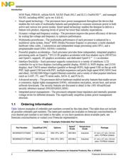
1.1 Ordering Information . . . . . . . . . . . . . . . . . . . . . . . . 2
1.2 Features . . . . . . . . . . . . . . . . . . . . . . . . . . . . . . . . . 4
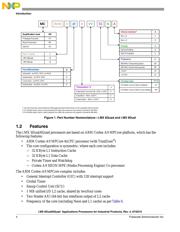
1.3 Updated Signal Naming Convention . . . . . . . . . . . . 7
2 Architectural Overview . . . . . . . . . . . . . . . . . . . . . . . . . . . 8
2.1 Block Diagram . . . . . . . . . . . . . . . . . . . . . . . . . . . . . 8
3 Modules List . . . . . . . . . . . . . . . . . . . . . . . . . . . . . . . . . . . 9
3.1 Special Signal Considerations. . . . . . . . . . . . . . . . 17
3.2 Recommended Connections for Unused Analog
Interfaces. . . . . . . . . . . . . . . . . . . . . . . . . . . . . . . . 17
4 Electrical Characteristics. . . . . . . . . . . . . . . . . . . . . . . . . 18
4.1 Chip-Level Conditions . . . . . . . . . . . . . . . . . . . . . . 18
4.2 Power Supplies Requirements and Restrictions . . 31
4.3 Integrated LDO Voltage Regulator Parameters. . . 32
4.4 PLL Electrical Characteristics . . . . . . . . . . . . . . . . 34
4.5 On-Chip Oscillators . . . . . . . . . . . . . . . . . . . . . . . . 35
4.6 I/O DC Parameters . . . . . . . . . . . . . . . . . . . . . . . . 36
4.7 I/O AC Parameters . . . . . . . . . . . . . . . . . . . . . . . . 40
4.8 Output Buffer Impedance Parameters. . . . . . . . . . 45
4.9 System Modules Timing . . . . . . . . . . . . . . . . . . . . 48
4.10 General-Purpose Media Interface (GPMI) Timing. 64
4.11 External Peripheral Interface Parameters . . . . . . . 73
5 Boot Mode Configuration . . . . . . . . . . . . . . . . . . . . . . . 135
5.1 Boot Mode Configuration Pins. . . . . . . . . . . . . . . 135
5.2 Boot Devices Interfaces Allocation . . . . . . . . . . . 136
6 Package Information and Contact Assignments . . . . . . 138
6.1 Updated Signal Naming Convention . . . . . . . . . . 138
6.2 21 x 21 mm Package Information . . . . . . . . . . . . 138
7 Revision History . . . . . . . . . . . . . . . . . . . . . . . . . . . . . . 160
页面指南