

下载
For technical support and more information, see inside back cover or visit www.ti.com/powertrends
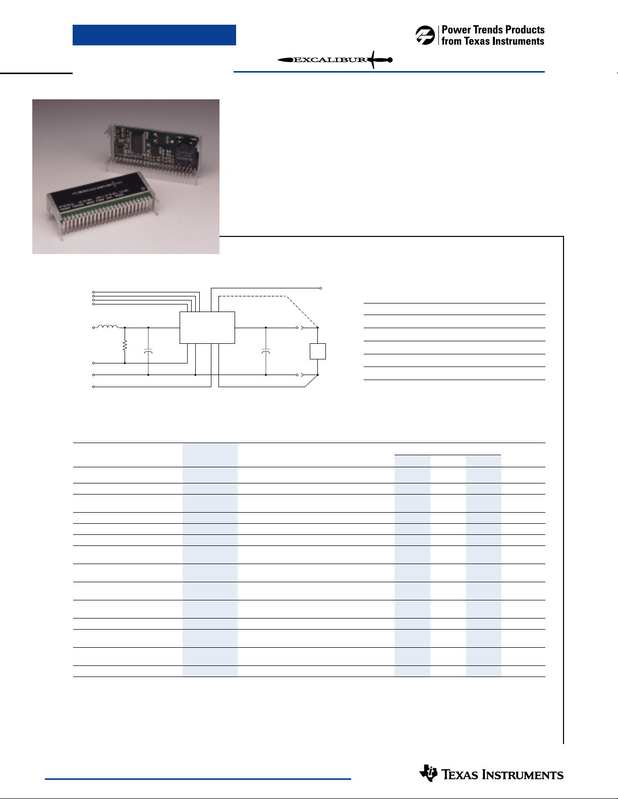
Standard Application
PT6702—3.3V
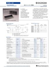
The PT6702 is 13Amp fully integrated
switching regulator housed in a unique, space-
saving package. The PT6702 operates from
+3.3V input to provide a high-performance,
low-voltage power source for the industry’s
latest µPs, DSPs, and bus drivers.
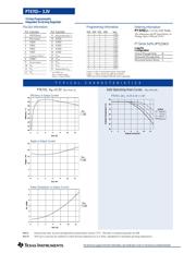
The output is programmable from 1.3V to
2.05V with a 4-bit input, compatible with
Intel’s Pentium
®
II Processor.
The PT6702 has short circuit protection,
a “Power Good” output, and an over-voltage
protection (OVP) drive output.
• +3.3V Input
• 4-bit Programmable:
1.3V to 2.05V
• High Efficiency
• Differential Remote Sense
• Short Circuit Protection
• Over-Voltage Drive
• Power Good Signal
• Space Saving SIP Package
• Solderable Copper Case
C
in
= Required 1000µF electrolytic
C
out
= Required 330µF electrolytic
L1 = Optional 1µH input choke
R1 = Required 10kΩ pull-up when using Pwr Good signal. Pwr good
output is high when the output voltage is within specification.
Specifications
Characteristics
PT6702 SERIES
(T
a
= 25°C unless noted) Symbols Conditions Min Typ Max Units
Output Current I
o
T
a
= +60°C, 200 LFM, pkg N 0.1
(1)
— 13.0
A
T
a
= +25°C, natural convection 0.1
(1)
— 13.0
Input Voltage Range V
in
0.1A ≤ I
o
≤ 13.0A 3.1
(2)
— 3.6 V
Output Voltage Tolerance ∆V
o
V
in
= +3.3V, I
o
= 13.0A
V
o-0.03 — Vo+0.03 V
–40°C ≤ T
a
≤ +85°C
Line Regulation Reg
line
3.1V ≤ V
in
≤ 3.6V, I
o
= 13.0A — ±10 — mV
Load Regulation Reg
load
V
in
= +3.3V, 0.1 ≤ I
o
≤ 13.0A — ±20 — mV
V
o
Ripple/Noise V
n
V
in
= +3.3V, I
o
= 13.0A — 50 — mV
Transient Response t
tr
I
o
step between 6A and 12A — 50 — µSec
with C
out
= 330µF V
os
V
o
over/undershoot — 100 — mV
Efficiency η V
in
= +3.3V, I
o
= 8A V
o
= 1.8V — 86 — %
V
o
= 1.5V — 84 — %
Switching Frequency ƒ
o
3.1V ≤ V
in
≤ 3.6V
300 350 400 kHz
0.1A ≤ I
o
≤ 13.0A
Absolute Maximum T
a
Over V
in and
I
o
Ranges
–40
(3)
— +85
(4)
°C
Operating Temperature Range
Storage Temperature T
s
— –40 — +125 °C
Mechanical Shock Per Mil-STD-883D, Method 2002.3
1 msec, Half Sine, mounted to a fixture — 500 — G’s
Mechanical Vibration Per Mil-STD-883D, Method 2007.2,
—15—G’s
20-2000 Hz, Soldered in a PC board
Weight — — — 26 — grams
Notes:
(1) ISR-will operate down to no load with reduced specifications.
(2) The minimum input voltage is 3.1V or V
out
+1.1V, whichever is greater.
(3) For operation below 0°C, Cin and Cout must have stable characteristics. Use either low ESR tantalum or Oscon® capacitors.
(4) See Safe Operating Area curves.
(5) If the remote sense ground is not used, pin 7 must be connected to pin 8 for optimal output voltage accuracy.
Output Capacitors:
The PT6702 requires a minimum ouput capacitance of 330µF for proper operation. The maximum allowable output capacitance is 15,000µF.
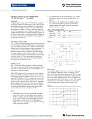
Input Filter:
An input filter is optional for most applications. The input inductor must be sized to handle 10.0ADC with a typical value of 1µH. The input capacitance must
be rated for a minimum of 2.0Arms of ripple current. For transient or dynamic load applications, additional capacitance may be required.
SLTS070A
(Revised 10/31/2000)
PT6702
10 - 12
14 - 18
19 - 22
2
V
IN
GND
1µH
GND
V
OUT
C
OUT
+
C
IN
+
13
233
L1
PWR GOOD
LOAD
REMOTE SENSE (+)
REMOTE SENSE (-)
VID1
VID2
VID3
PROGRAMMING PINS
456
STBY*
8
VID0
OVP DRV
1
R1
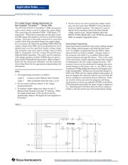
13 Amp Programmable
Integrated Switching Regulator
Patent pending on package assembly
New Space-Saving Package
PT6700 Product Family
Input Vout OVP/ Requires
Voltage Adjust Pwr Good +12V Bias
PT6701 5V VID 3
PT6702 3.3V VID 3
PT6705 5V Resistor 3
PT6715 5V Resistor
PT6721 12V VID 3
PT6725 12V Resistor