

下载

1998 Microchip Technology Inc. DS30274B-page 1
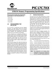
PIC17C7XX
This document includes the programming
specifications for the following devices:
• PIC17C752
• PIC17C756
• PIC17C756A
• PIC17C762
• PIC17C766
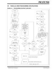
1.0 PROGRAMMING THE
PIC17C7XX
The PIC17C7XX is programmed using the TABLWT
instruction. The table pointer points to the internal
EPROM location start. Therefore, a user can program
an EPROM location while executing code (even from
internal EPROM). This programming specification
applies to PIC17C7XX devices in all packages.
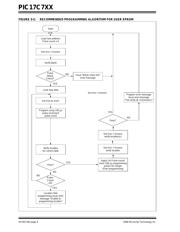
For the convenience of a programmer developer, a
“program & verify” routine is provided in the on-chip test
program memory space. The program resides in ROM
and not EPROM, therefore, it is not erasable. The “pro-
gram/verify” routine allows the user to load any
address, program a location, verify a location or incre-
ment to the next location. It allows variable program-
ming pulse width.
The PIC17C7XX group of the High End Family has
added a feature that allows the serial programming of
the device. This is very useful in applications where it is
desirable to program the device after it has been man-
ufactured into the users system (In-circuit Serial Pro-
gramming (ISP)). This allows the product to be shipped
with the most current version of the firmware, since the
microcontroller can be programmed just before final
test as opposed to before board manufacture. Devices
may be serialized to make the product unique, “special”
variants of the product may be offered, and code
updates are possible. This allows for increased design
flexibility.
1.1 Hardware Requirements
Since the PIC17C7XX under programming is actually
executing code from “boot ROM,” a clock must be pro-
vided to the part. Furthermore, the PIC17C7XX under
programming may have any oscillator configuration
(EC, XT, LF or RC). Therefore, the external clock driver
must be able to overdrive pulldown in RC mode. CMOS
drivers are required since the OSC1 input has a
Schmitt trigger input with levels (typically) of 0.2 V
DD
and 0.8 VDD. See the PIC17C7XX data sheet
(DS30289) for exact specifications.
The PIC17C7XX requires two programmable power
supplies, one for V
DD (3.0V to 5.5V recommended) and
one for V
PP (13 ± 0.25V). Both supplies should have a
minimum resolution of 0.25V.
The PIC17C7XX uses an intelligent algorithm. The
algorithm calls for program verification at V
DDmin as
well as V
DDmax. Verification at VDDmin guarantees
good “erase margin”. Verification at V
DDmax guaran-
tees good “program margin.” Three times (3X)
additional pulses will increase program margin beyond
V
DDmax and insure safe operation in user system.
The actual programming must be done with V
DD in the
V
DDP range (Parameter PD1).
V
DDP = VDD range required during programming.
V
DDmin. = minimum operating VDD spec. for the part.
V
DDmax. = maximum operating VCC spec for the part.
Programmers must verify the PIC17C7XX at its speci-
fied V
DDmax and VDDmin levels. Since Microchip may
introduce future versions of the PIC17C7XX with a
broader VDD range, it is best that these levels are user
selectable (defaults are ok). Blank checks should be
performed at V
DDMIN.
Note: Any programmer not meeting these
requirements may only be classified as
“prototype” or “development” programmer
but not a “production” quality programmer.
EPROM Memory Programming Specifications