

下载

1. General description
The PCA9551 LED blinker blinks LEDs in I
2
C-bus and SMBus applications where it is
necessary to limit bus traffic or free up the I
2
C-bus master's (MCU, MPU, DSP, chip set,
etc.) timer. The uniqueness of this device is the internal oscillator with two programmable
blink rates. To blink LEDs using normal I/O expanders like the PCF8574 or PCA9554, the
bus master must send repeated commands to turn the LED on and off. This greatly
increases the amount of traffic on the I
2
C-bus and uses up one of the master's timers.
The PCA9551 LED blinker instead requires only the initial set-up command to program
BLINK RATE 1 and BLINK RATE 2 (i.e., the frequency and duty cycle) for each individual
output. From then on, only one command from the bus master is required to turn each
individual open-drain output on, off, or to cycle at BLINK RATE 1 or BLINK RATE 2.
Maximum output sink current is 25 mA per bit and 100 mA per package.
Any bits not used for controlling the LEDs can be used for General Purpose parallel
Input/Output (GPIO) expansion.
The active LOW hardware reset pin (RESET) and Power-On Reset (POR) initializes the
registers to their default state, all zeroes, causing the bits to be set HIGH (LED off).
Three hardware address pins on the PCA9551 allow eight devices to operate on the same
bus.
The newer Fast-mode Plus PCA9634 8-bit LED controller offers an individual PWM
dimming control for each channel for better color mixing capabilities with a global PWM for
dimming or blinking all channels at the same time. There are 126 possible address
combinations and the maximum output sink current is 25 mA per bit and 200 mA per
package.
2. Features
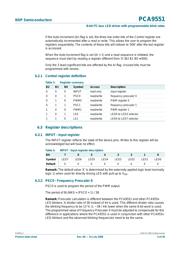
n 8 LED drivers (on, off, flashing at a programmable rate)
n 2 selectable, fully programmable blink rates (frequency and duty cycle) between
0.148 Hz and 38 Hz (6.74 seconds and 0.026 seconds)
n Input/outputs not used as LED drivers can be used as regular GPIOs
n Internal oscillator requires no external components
n I
2
C-bus interface logic compatible with SMBus
n Internal power-on reset
n Noise filter on SCL/SDA inputs
n Active LOW reset input
n 8 open-drain outputs directly drive LEDs to 25 mA
n Edge rate control on outputs
PCA9551
8-bit I
2
C-bus LED driver with programmable blink rates
Rev. 08 — 31 July 2008 Product data sheet
页面指南