
下载

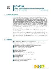
1. General description
The PCA9550 LED blinker blinks LEDs in I
2
C-bus and SMBus applications where it is
necessary to limit bus traffic or free up the I
2
C master's (MCU, MPU, DSP, chip set, etc.)
timer. The uniqueness of this device is the internal oscillator with two programmable blink
rates. To blink LEDs using normal I/O expanders like the PCF8574 or PCA9554, the bus
master must send repeated commands to turn the LED on and off. This greatly increases
the amount of traffic on the I
2
C-bus and uses up one of the master's timers. The PCA9550
LED blinker instead requires only the initial set-up command to program BLINK RATE 1
and BLINK RATE 2 (i.e., the frequency and duty cycle). From then on, only one command
from the bus master is required to turn each individual open-drain output ON, OFF, or to
cycle at BLINK RATE 1 or BLINK RATE 2. Maximum output sink current is 25 mA per bit
and 50 mA per package.
Any bits not used for controlling the LEDs can be used for General Purpose parallel
Input/Output (GPIO) expansion.
The active LOW hardware reset pin (RESET) and Power-On Reset (POR) initializes the
registers to their default state, all zeroes, causing the bits to be set HIGH (LED off).
One hardware address pin on the PCA9550 allows two devices to operate on the same
bus.
2. Features
n 2 LED drivers (on, off, flashing at a programmable rate)
n 2 selectable, fully programmable blink rates (frequency and duty cycle) between
0.172 Hz and 44 Hz (5.82 seconds and 0.023 second)
n Input/output not used as LED drivers can be used as regular GPIOs
n Internal oscillator requires no external components
n I
2
C-bus interface logic compatible with SMBus
n Internal power-on reset
n Noise filter on SCL/SDA inputs
n Active LOW reset input
n 2 open-drain outputs directly drive LEDs to 25 mA
n Controlled edge rates to minimize ground bounce
n No glitch on power-up
n Supports hot insertion
n Low standby current
n Operating power supply voltage range of 2.3 V to 5.5 V
n 0 kHz to 400 kHz clock frequency
PCA9550
2-bit I
2
C-bus LED driver with programmable blink rates
Rev. 05 — 13 October 2008 Product data sheet
页面指南