

下载
0
500
1,000
1,500
2,000
2,500
3,000
3,500
-50 -25 0 25 50 75 100 125 150 175
VTEMP VOLTAGE (mV)
TEMPERTURE (C)
J2 (-5.166mV/°C)
J3 (-7.752mV/°C)
J4 (-10.339mV/°C)
J5 (-12.924mV/°C)
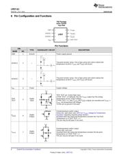
C101
V
DD
Supply
(+2.4V to +5.5V)
GND
V
DD
T
OVER
V
TEMP
TRIP TEST
Microcontroller
LM57
ADC Input
T
OVER
Digital In
Digital Out
SENSE1
SENSE2
Analog
R
SENSE1
R
SENSE2
Product
Folder
Sample &
Buy
Technical
Documents
Tools &
Software
Support &
Community
LM57-Q1
SNIS191 –JULY 2015
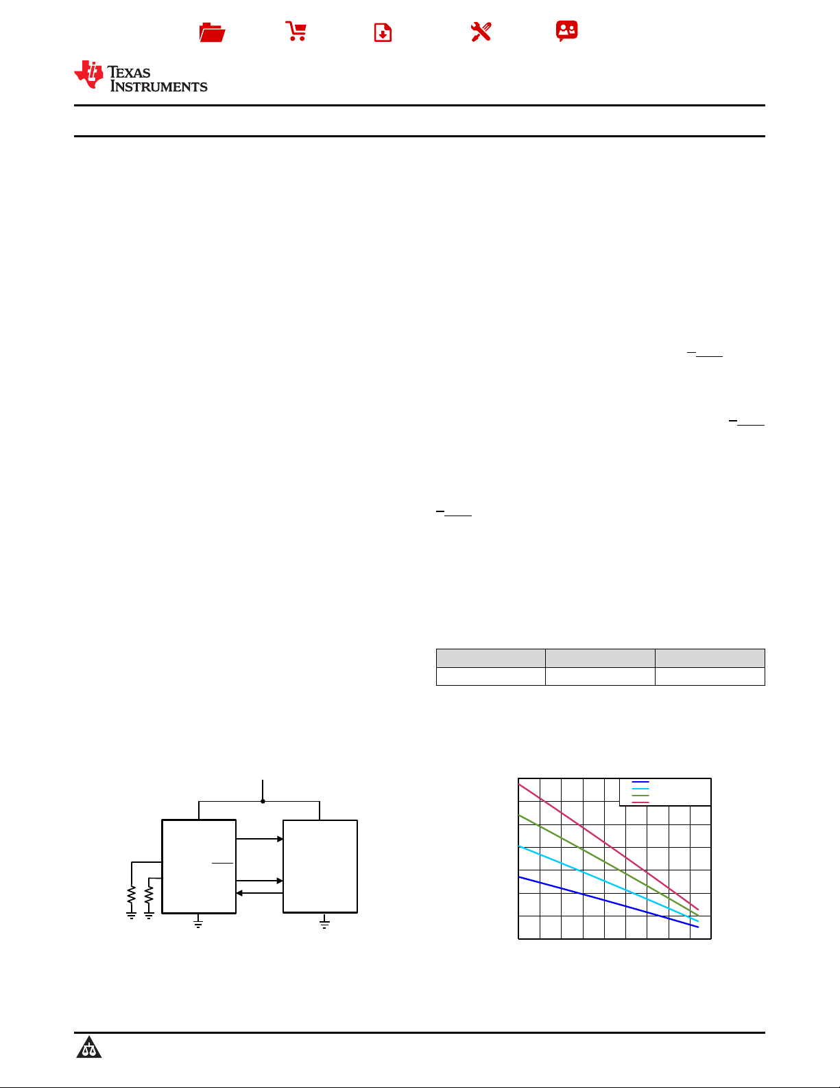
LM57-Q1 Resistor-Programmable Temperature Switch and Analog Temperature Sensor
1 Features 3 Description
The LM57-Q1 device is a precision, dual-output,
1
• LM57-Q1 is AEC-Q100 Grade 1/Grade 0/Grade 0
temperature switch with analog temperature sensor
Extended (Qualified and Manufactured on an
output for wide temperature applications such as
Automotive Grade Flow), for commercial device
automotive grade. The trip temperature (T
TRIP
) is
see LM57 datasheet
selected from 256 possible values in the range of
• Trip Temperature Set by External Resistors with
–40°C to +160°C. The V
TEMP
is a class AB analog
Accuracy of ±1.7°C or ±2.3° C from -40°C to
voltage output that is proportional to temperature with
a programmable negative temperature coefficient
+150°C
(NTC). Two external 1% resistors set the T
TRIP
and
• Resistor Tolerance Contributes Zero Error
V
TEMP
slope. The digital and analog outputs enable
• Push-Pull and Open-Drain Switch Outputs
protection and monitoring of system thermal events.
• Wide Operating Temperature and Trip-
Built-in thermal hysteresis (T
HYST
) prevents the digital
Temperature Range of −50°C to 160°C,
outputs from oscillating. The T
OVER
and T
OVER
digital
with Allowable Excursions up to 170°C
outputs will assert when the die temperature exceeds
• Very Linear Analog V
TEMP
Temp Sensor Output
T
TRIP
and will de-assert when the temperature falls
with ±0.8°C or ±1.3°C Accuracy from -40°C to
below a temperature equal to T
TRIP
minus T
HYST
.
+150°C
T
OVER
is active-high with a push-pull structure. T
OVER
• Short-Circuit Protected Analog and Digital Outputs
is active-low with an open-drain structure. Tying
T
OVER
to TRIP-TEST will latch the output after it trips.
• Latching Function for Digital Outputs
The output can be cleared by forcing TRIP-TEST low.
• TRIP-TEST Pin Allows In-System Testing
Driving the TRIP-TEST high will assert the digital
• Low Power Minimizes Self-Heating to Under
outputs. A processor can check the state of T
OVER
or
0.02°C
T
OVER
, confirming they changed to an active state.
This allows for in-situ verification that the comparator
2 Applications
and output circuitry are functional after system
assembly. When TRIP-TEST is high, the trip-level
• Automotive
reference voltage appears at the V
TEMP
pin. The
• Factory Automation
system could then use this voltage to calculate the
• Industrial
threshold of the LM57-Q1.
• Down Hole
Device Information
(1)(2)
• Avionics
PART NUMBER PACKAGE BODY SIZE (NOM)
• Telecom Infrastructure
LM57-Q1 TSSOP (8) 3.00 mm × 6.40 mm
(1) For all available packages, see the orderable addendum at
the end of the data sheet.
(2) For device comparison see Device Comparison Table.
LM57-Q1 Overtemperature Alarm
Temperature Transfer Function
1
An IMPORTANT NOTICE at the end of this data sheet addresses availability, warranty, changes, use in safety-critical applications,
intellectual property matters and other important disclaimers. PRODUCTION DATA.
页面指南