


下载

Application Report
SNLA228–October 2014
Understanding EEPROM Programming for High Speed
Repeaters and Mux Buffers
Michael Lu, Prescott Siao
ABSTRACT
System designers often use EEPROM (Electrically Erasable Programmable Read-Only Memory) to
program a set of customized high speed repeater and mux buffer start-up settings that are different from
the default. Using the information here will make repeater EEPROM configuration and programming easy
to implement and understand. This application note addresses SMBus-to-EEPROM mapping for 2-channel
repeaters, 8-channel repeaters (8-channel uni-directional and 4-lane bi-directional), and 2:1/1:2 mux
buffers. In addition, this application note provides guidance and several examples regarding how to read
the Intel hex file format as it relates to each programmed TI device. With a complete understanding of how
to program and interpret EEPROM hex files for TI’s 2-channel repeaters, 8-channel repeaters, and 2:1/1:2
mux buffers, system designers are better equipped to generate their own customized hex files and
increase the efficiency of their final designs. The information in this Application Report applies to the
DS80PCIxxx, DS100BRxxx, and DS125BRxxx drivers as well as the DS100MB203 and DS125MB203
mux buffers.
Contents
1 Introduction .................................................................................................................. 2
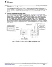
2 EEPROM Physical Configuration ......................................................................................... 3
2.1 EEPROM Configuration for Single Device ...................................................................... 3
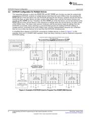
2.2 EEPROM Configuration for Multiple Devices .................................................................. 4
3 SMBus-to-EEPROM Mapping.............................................................................................. 5
4 EEPROM Hex File Format ................................................................................................. 9
5 EEPROM Device Data Fundamentals................................................................................... 10
5.1 Base Header....................................................................................................... 10
5.2 Address Map Header ............................................................................................. 10
5.3 Cyclic Redundancy Check (CRC) Calculation................................................................. 11
5.4 Number of Devices versus Number of Slots................................................................... 11
6 Example 1: EEPROM Hex File for 1 Device, CRC Disabled......................................................... 12
7 Example 2: EEPROM Hex File for 4 EEPROM slots, CRC Enabled................................................ 13
8 Example 3: EEPROM Hex File for 12 Devices, CRC Disabled...................................................... 14
9 Summary .................................................................................................................... 15
10 References.................................................................................................................. 15
All trademarks are the property of their respective owners.
1
SNLA228–October 2014 Understanding EEPROM Programming for High Speed Repeaters and Mux
Buffers
Submit Documentation Feedback
Copyright © 2014, Texas Instruments Incorporated