
下载

© Semiconductor Components Industries, LLC, 2011
October, 2011 − Rev. 25
1 Publication Order Number:
CAT5113/D
CAT5113
100-Tap Digitally Program-
mable Potentiometer (DPP)
Description
The CAT5113 is a single digitally programmable potentiometer
(DPP) designed as an electronic replacement for mechanical
potentiometers. Ideal for automated adjustments on high volume
production lines, they are also well suited for applications where
equipment requiring periodic adjustment is either difficult to access or
located in a hazardous or remote environment.
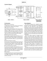
The CAT5113 contains a 100−tap series resistor array connected
between two terminals R
H
and R
L
. An up/down counter and decoder
that are controlled by three input pins, determines which tap is
connected to the wiper, R
W
. The wiper setting, stored in nonvolatile
memory, is not lost when the device is powered down and is
automatically reinstated when power is returned. The wiper can be
adjusted to test new system values without affecting the stored setting.
Wiper−control of the CAT5113 is accomplished with three input
control pins, CS
, U/D, and INC. The INC input increments the wiper
in the direction which is determined by the logic state of the U/D
input.
The CS
input is used to select the device and also store the wiper
position prior to power down.
The digitally programmable potentiometer can be used as a
three-terminal resistive divider or as a two-terminal variable resistor.
Features
• 100−position Linear Taper Potentiometer
• Non−volatile EEPROM Wiper Storage
• 10 nA Ultra−low Standby Current
• Single Supply Operation: 2.5 V − 6.0 V
• Increment Up/Down Serial Interface
• Resistance Values: 1 kW, 10 kW, 50 kW and 100 kW
• Available in PDIP, SOIC, TSSOP and MSOP Packages
• These Devices are Pb−Free, Halogen Free/BFR Free and are RoHS
Compliant
Applications
• Automated Product Calibration
• Remote Control Adjustments
• Offset, Gain and Zero Control
• Tamper−proof Calibrations
• Contrast, Brightness and Volume Controls
• Motor Controls and Feedback Systems
• Programmable Analog Functions
http://onsemi.com
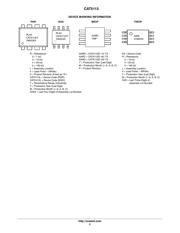
PIN CONFIGURATIONS
R
H
R
WB
R
L
U/D
INC
V
CC
CS
1
See detailed ordering and shipping information in the package
dimensions section on page 9 of this data sheet.
ORDERING INFORMATION
SOIC−8
V SUFFIX
CASE 751BD
MSOP−8
Z SUFFIX
CASE 846AD
GND
PDIP (L), SOIC (V),
MSOP (Z)
PDIP−8
L SUFFIX
CASE 646AA
TSSOP−8
Y SUFFIX
CASE 948AL
Increment ControlINC
Up/Down ControlU/D
Potentiometer High TerminalR
H
GroundGND
Wiper TerminalR
W
Potentiometer Low TerminalR
L
FunctionPin Name
PIN FUNCTION
Chip SelectCS
Supply VoltageV
CC
TSSOP (Y)
(Top Views)
GND
R
H
U/D
INC
R
WB
CS
V
CC
R
L
1
页面指南