

下载
AN-1044
APPLICATION NOTE
One Technology Way • P. O. Box 9106 • Norwood, MA 02062-9106, U.S.A. • Te l: 781.329.4700 • Fax: 781.461.3113 • www.analog.com
Programming the AD5932 for Frequency Sweep and Single Frequency Outputs
by Liam Riordan
Rev. A | Page 1 of 4
INTRODUCTION
This application note details how to program the output of the
AD5932 to sweep frequency from 1 MHz to 10 MHz. Then,
when the user has discovered the strongest frequency point on
the spectrum, the part can be selected to only transmit a sine
wave at that particular frequency.
POWERING UP THE AD5932
The AD5932 is powered up in an undefined state. The registers
(control and frequency) contain invalid data and must be set to
a known value by the user. The control register should be the
first register to be programmed because this sets up the part.
Note that a write to the control register automatically resets the
internal state machines and provides an analog output of midscale
because it performs the same function as the INTERRUPT pin.
Typically, this is followed by a serial loading of all the required
scan parameters. The DAC output remains at midscale until a
frequency scan is started using the CTRL pin.
To set up the part in sweep mode, the following registers must
be written to:
• Control register × 1
• Start frequency registers (F
START
) × 2
• Frequency increment (or delta frequency) register (f) × 1
• Number of increments register (N
INCR
) × 1
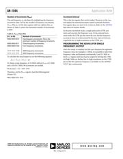
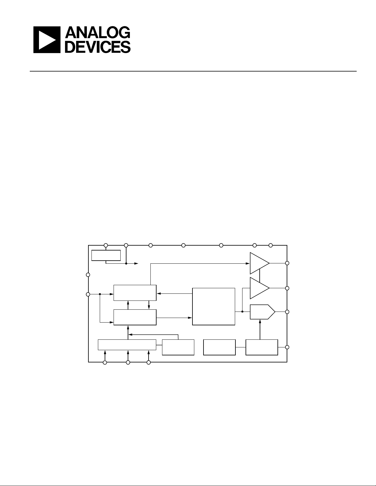
FUNCTIONAL BLOCK DIAGRAM
AD5932
DVDD CAP/2.5V DGND INTERRUPT ST
A
NDBY
A
GND
A
V
DD
VCC
2.5V
SYNC
MCLK
CTRL
FSYNC
SYNCOUT
MSBOUT
VOUT
COMP
SCLK SDATA
DATA AND CONTROL
FREQUENCY
CONTROLLER
INCREMENT
CONTROLLER
CONTROL
REGISTER
ON-BOARD
REFERENCE
FULL-SCALE
CONTROL
24-BIT
PIPELINED
DDS CORE
10-BIT
DAC
SERIAL INTERFACE
REGULATOR
DATA INCR
BUFFER
BUFFER
/
24
08425-001
Figure 1.