


下载

Document Number: 95179 For technical questions within your region, please contact one of the following: www.vishay.com
Revision: 11-Jun-10 DiodesAmericas@vishay.com
, DiodesAsia@vishay.com, DiodesEurope@vishay.com 1
VISHAY SEMICONDUCTORS
Rectifiers
Application Note
PowerTab
TM
Mounting Guidelines
APPLICATION NOTE
1.0 INTRODUCTION
The PowerTab
TM
package has been designed to fill the gap
in the market between the TO-247, more expensive metal
case devices and non-isolated power modules. It is the
natural replacement for metal case outlines such as
DO-203AA and DO-203AB, but it is also suitable for new
innovative solutions, thanks to a package outline that
combines low profile, excellent die to footprint ratio and
sturdy connectivity. It utilises a large lead for high current
connection, carrying both a mounting hole and PCB insertion
pins. The body is compatible with a TO-218 outline, with an
exposed heatsink and non-isolated mounting hole.
It is anticipated that the devices would find typical
applications in busbar assemblies or finned heatsinks,
reducing component count and cost of ownership.
2.0 SCOPE
This application note covers the various fixment methods
that are possible with this device, and the associated thermal
properties resulting from their use:
a. Optimum mounting torque
b. Type of fixings
c. Effect of torque on thermal resistance (“wet” and “dry”)
d. Effect of pressure on contact thermal resistance (“wet”
and “dry”)
3.0 MECHANICAL CONSIDERATIONS
3.1 TYPE OF FIXINGS
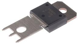
The PowerTab possesses mounting holes in the tab and
lead for electrically connecting the device to heatsinks or
busbars. The lead also carries PCB insertion pins so that the
lead end may be soldered into a board.
Fig. 1
3.2 TAB CONNECTION
Using the mounting hole in the tab allows a designer to
attach the PowerTab to a heatsink. The tab of a PowerTab
acts as one of the terminals. There is no common additional
lead, so the mounting hole contact must be very good, with
the heatsink forming part of the circuit. For the best results
the surface of the heatsink must be as smooth and flat as
possible to maximise the contact area of the tab. A good
flatness specification would be 0.02 mm (0.0007") maximum
per 10 mm (0.393"). Ensure also that the heatsink mounting
hole has been deburred.
The mounting hole in the tab is designed to accept a M4
screw, No. 6-32 screw or 6-40 screw. A self tapping type
screw may also be used. However, only a certain type of
screw and washer may be used to attach the tab to the
heatsink because of the proximity of the mounting hole to the
plastic body.
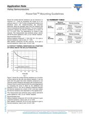
The recommended method of attachment is a socket headed
M4 screw, with a plain washer, as shown in the figure 2. The
washer used must be no larger than the diameter of the
socket head. If a larger washer is used, it can bear directly on
the edge of the plastic body, causing the body to crack when
the screw is tightened. The largest possible diameter washer
that may be used is 7.2 mm (0.283"). An alternative is a
suitably sized rectangular washer.
Tab (header)
Lead
PCB insertion
pins
Stress relief slots