
下载

User's Guide
SLVU333A–August 2009–Revised March 2012
TPS73401DRV EVM
This User’s Guide describes the characteristics, operation, and use of the TPS73401DRVEVM-527. This
EVM demonstrates the Texas Instruments TPS73401, a Low Drop Out (LDO) linear regulator in a
2mm x 2mm SON-6 package that is capable of 250mA of output current. This user’s guide includes setup
instructions, a schematic diagram, thermal guidelines, a bill of materials (BOM), and PCB layout drawings
for the evaluation module.
Contents
1 Introduction .................................................................................................................. 2
1.1 Related Documentation From Texas Instruments ............................................................. 2
1.2 TPS73401DRVEVM Specifications .............................................................................. 2
2 Setup ......................................................................................................................... 2
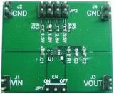
2.1 Input / Output Connector Descriptions .......................................................................... 2
3 Operation ..................................................................................................................... 3
3.1 Fixed Output TPS734xx ........................................................................................... 3
4 Thermal Guidelines ......................................................................................................... 3
4.1 Thermal Considerations ........................................................................................... 3
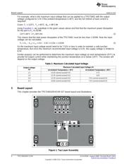
5 Board Layout ................................................................................................................ 4
6 Schematic and Bill of Materials ........................................................................................... 7
6.1 Schematic ........................................................................................................... 7
6.2 Bill of Materials (BOM) ............................................................................................ 8
7 Related Documentation From Texas Instruments ...................................................................... 8
List of Figures
1 Top Layer Assembly........................................................................................................ 4
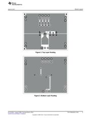
2 Top Layer Routing .......................................................................................................... 5
3 Bottom Layer Routing ...................................................................................................... 5
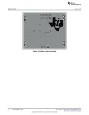
4 Bottom Layer Assembly.................................................................................................... 6
5 TPS73401DRVEVM-527 Schematic ..................................................................................... 7
List of Tables
1 Output Voltage Setting ..................................................................................................... 3
2 Maximum Calculated Input Voltage ...................................................................................... 4
3 Bill of Materials.............................................................................................................. 8
1
SLVU333A–August 2009–Revised March 2012 TPS73401DRV EVM
Submit Documentation Feedback
Copyright © 2009–2012, Texas Instruments Incorporated