
下载

User's Guide
SLVUAJ6A–September 2015–Revised November 2015
TPS65321EVM (HVL125A) User Guide
The Texas Instruments TPS65321EVM evaluation module (EVM) helps designers evaluate the operation
and performance of the TPS65321-Q1, a switch-mode DC-DC step-down converter with an integrated
low-dropout voltage regulator (LDO). This user guide describes how to setup and configure the EVM for
operation. The document includes the board layout, schematic, and bill of materials for the EVM.
Contents
1 Introduction ................................................................................................................... 1
2 Schematic, Bill of Materials, and Layout ................................................................................. 1
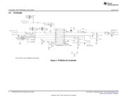
2.1 Schematic............................................................................................................ 2
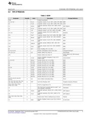
2.2 Bill of Materials...................................................................................................... 3
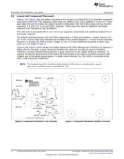
2.3 Layout and Component Placement............................................................................... 4
3 Setup and Operation ....................................................................................................... 5
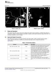
3.1 Input and Output Connectors ..................................................................................... 5
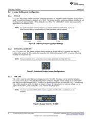
3.2 Jumper Setting and Configuration................................................................................ 6
3.3 Test Point Description.............................................................................................. 7
3.4 Basic Operation..................................................................................................... 7
List of Figures
1 TPS65321-Q1 Schematic................................................................................................... 2
2 Component Placement—Top Overview .................................................................................. 4
3 Component Placement—Bottom Overview .............................................................................. 4
4 Layout—Top.................................................................................................................. 4
5 Layout—Bottom.............................................................................................................. 4
6 Switching Frequency Jumper Settings.................................................................................... 6
7 Enable and Disable Jumper Configurations.............................................................................. 6
8 Supply-Selection for LDO................................................................................................... 6
List of Tables
1 BOM .......................................................................................................................... 3
2 Terminal Descriptions ....................................................................................................... 5
3 Configured Output Voltages and Maximum Currents................................................................... 7
1 Introduction
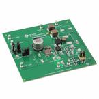
The HVL125A is a fully assembled PCB design for evaluation of TPS65321-Q1, a device containing a DC-
DC step-down converter and a low-dropout voltage regulator.
2 Schematic, Bill of Materials, and Layout
This section provides a detailed description of the schematic, bill of materials (BOM), and layout.
Eco-mode, PowerPad are trademarks of Texas Instruments.
All other trademarks are the property of their respective owners.
1
SLVUAJ6A–September 2015–Revised November 2015 TPS65321EVM (HVL125A) User Guide
Submit Documentation Feedback
Copyright © 2015, Texas Instruments Incorporated