下载

User's Guide
SLVU270 – September 2008
TPS54160EVM-230
Contents
1 Introduction ................................................................................................................... 2
1.1 Background .......................................................................................................... 2
2 Connector Description....................................................................................................... 2
2.1 Input/Output Connector Descriptions............................................................................. 2
3 Performance Specifications ................................................................................................ 3
3.1 Top Converter Specification ....................................................................................... 3
3.2 Bottom Converter Specification ................................................................................... 4
4 Test Results .................................................................................................................. 6
5 Board Layout ................................................................................................................ 11
5.1 Layout ............................................................................................................... 11
6 Schematic and Bill of Materials ........................................................................................... 17
6.1 Schematic .......................................................................................................... 17
6.2 Bill of Materials .................................................................................................... 18
List of Figures
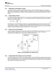
1 Synchronization to an External Clock .................................................................................... 5
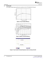
2 Top Converter Efficiency .................................................................................................... 6
3 Bottom Converter Efficiency ............................................................................................... 6
4 Top Converter Transient Response, 0.5A to 1.5A step, Vin=42V ..................................................... 6
5 Bottom Converter Transient Response, 0.5A to 1.5A step, Vin=48V ................................................. 7
6 Top Converter Output Voltage Ripple, Vin=42V, Iout=1.5A ............................................................ 7
7 Bottom Converter Output Voltage Ripple, Vin=60.0V, Iout=1.5A ..................................................... 7
8 Top Converter Input Voltage Ripple, Vin=42.0V, Iout=1.5A ........................................................... 8
9 Bottom Converter Input Voltage Ripple, Vin=48.0V, Iout=1.5A ........................................................ 8
10 Top Converter Start-up relative to Vin, Vin=42V, Iout=1.5A ........................................................... 8
11 Top Converter UVLO relative to Vin, Iout=1.5A ......................................................................... 9
12 Bottom Converter Start-up relative to Vin, Vin=60.0V, Iout=1.5A ..................................................... 9
13 Bottom Converter Start-up relative to EN, Vin=60.0V, Iout=1.5A ..................................................... 9
14 Bottom Converter Loop Response, Vin=36V, Iout=1.0A .............................................................. 10
15 Top Converter Loop Response, Vin=42V, Iout=1.0A .................................................................. 10
16 Assembly Layer............................................................................................................. 12
17 Top Layer Routing ......................................................................................................... 13
18 Layer 2 Routing ............................................................................................................. 14
19 Layer 3 Routing ............................................................................................................. 15
20 Bottom Layer Routing ...................................................................................................... 16
21 TPS54160EVM-230 Schematic .......................................................................................... 17
List of Tables
1 Top Converter Specifications............................................................................................... 4
2 Bottom Converter Specifications ........................................................................................... 4
3 TPS54160EVM-230 Bill of Materials – Top Converter ................................................................ 18
4 TPS54160EVM-230 Bill of Materials – Bottom Converter ............................................................ 18
SLVU270 – September 2008 TPS54160EVM-230 1
Submit Documentation Feedback

