
下载

1
SLVUA37A–March 2014–Revised October 2016
Submit Documentation Feedback
Copyright © 2014–2016, Texas Instruments Incorporated
TPD4E110DPW Evaluation Module
User's Guide
SLVUA37A–March 2014–Revised October 2016
TPD4E110DPW Evaluation Module
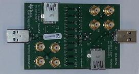
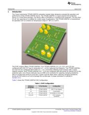
This user's guide describes the characteristics, operation, and use of the TPD4E110DPWEVM evaluation
module (EVM). This EVM includes 15 TPD4E110DPWs in various configurations for testing. Nine
TPD4E110DPWs are configured for IEC61000-4-2 compliance testing, two TPD4E110DPW are
configured for 4-port s-parameter analysis, and four are configured with USB 3.0 Type A connectors for
throughput analysis. Additionally, one of the TPD4E110DPWs for ESD testing also allows the capture of
clamping waveforms during an ESD event. This user's guide includes setup instructions, schematic
diagrams, a bill of materials, and printed-circuit board layout drawings for the evaluation module.
Contents
1 Introduction ................................................................................................................... 2
2 Definitions..................................................................................................................... 3
3 Setup .......................................................................................................................... 3
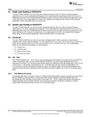
3.1 Single Layer Routing on SSRX/SSTX ........................................................................... 4
3.2 Double Layer Routing on SSRX/SSTX .......................................................................... 4
3.3 U3 and U4 ........................................................................................................... 4
3.4 U5 – U13 ............................................................................................................ 4
3.5 U9..................................................................................................................... 5
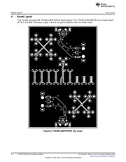
4 Board Layout ................................................................................................................. 6
5 Schematic..................................................................................................................... 8
6 Bill of Materials............................................................................................................... 9
List of Figures
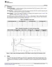
1 Ideal Contact Discharge Waveform of the Output Current of the ESD Simulator at 4-kV ......................... 3
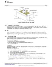
2 System Level ESD Test Setup............................................................................................. 5
3 TPD4E110DPWEVM Top Layer........................................................................................... 6
4 TPD4E110DPWEVM Bottom Layer....................................................................................... 7
5 TPD4E110DPWEVM Schematic........................................................................................... 8
List of Tables
1 EVM Configuration .......................................................................................................... 2
2 IEC61000-4-2 Test Levels ................................................................................................. 3
3 Waveform Parameters in Contact Discharge Mode..................................................................... 3