


下载

User's Guide
SLVU306 – April 2009
TLC5944EVM-358
This user’s guide describes the characteristics, setup, and use of the TLC5944EVM-358 Evaluation
Module (EVM). This EVM helps the user evaluate the features of the Texas Instruments TLC5944, which
is a 16-channel, constant-current LED driver. This user’s guide includes setup instructions, a schematic
diagram, a bill of materials, printed-circuit board layout drawings, and software instructions.
Contents
1 Introduction ................................................................................................................... 2
1.1 Requirements ....................................................................................................... 2
1.2 Related Documentation From Texas Instruments .............................................................. 3
2 Setup .......................................................................................................................... 3
2.1 Input/Output Connector Descriptions............................................................................. 4
2.2 Software Setup ...................................................................................................... 6
2.3 Hardware Setup ..................................................................................................... 6
3 Operation ..................................................................................................................... 7
3.1 Running the Software .............................................................................................. 7
3.2 Software Features .................................................................................................. 7
3.3 Hardware Features ................................................................................................ 11
4 Schematics, Board Layouts, and Bill of Materials ...................................................................... 12
4.1 Schematics ......................................................................................................... 12
4.2 Board Layouts ..................................................................................................... 19
4.3 Bill of Materials .................................................................................................... 28
List of Figures
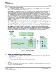
1 Board Connections .......................................................................................................... 3
2 TLC5944EVM Software Start-Up Screen ................................................................................. 7
3 TLC5944EVM Software with Ghosting Demo Enabled. ................................................................ 9
4 Information Bar ............................................................................................................. 10
5 HPA357A - Schematic 1 .................................................................................................. 12
6 HPA357A - Schematic 2 .................................................................................................. 13
7 HPA358A Schematic 1 .................................................................................................... 14
8 HPA358A Schematic 2 .................................................................................................... 15
9 HPA358A Schematic 3 .................................................................................................... 16
10 HPA358A Schematic 4 .................................................................................................... 17
11 HPA358A Schematic 5 .................................................................................................... 18
12 HPA357A Assembly Layer Routing ...................................................................................... 19
13 HPA357A Top Layer Routing ............................................................................................ 20
14 HPA357A Layer 2 Routing ................................................................................................ 21
15 HPA357A Layer 3 Routing ................................................................................................ 22
16 HPA357A Bottom Layer Routing ......................................................................................... 23
17 HPA358A Assembly Layer ............................................................................................... 24
18 HPA358A Top Layer ...................................................................................................... 25
19 HPA358A Layer 2 ......................................................................................................... 26
20 HPA358A Layer 3 .......................................................................................................... 27
21 HPA358A Bottom Layer Routing ......................................................................................... 28
List of Tables
SLVU306 – April 2009 TLC5944EVM-358 1
Submit Documentation Feedback