下载

User's Guide
SLLU174–January 2013
SN6501 Multi-Transformer EVM User’s Guide
This user’s guide explains how to quickly obtain the push-pull converter performance results with the
SN6501 evaluation module (EVM). This EVM provides five push-pull converters for various input-to-output
voltage conversions utilizing regulated and non-regulated outputs. All push-pull converters use low-power,
center-tapped transformers from Wurth-Electronics/Midcom whose designs have been optimized in form-
factor, turns ratio, and saturation product to operate in combination with the SN6501 transformer driver.
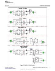
Table 1 lists the push-pull converter configurations with their associated transformers and Figure 3 shows
the EVM schematic.
Table 1. Push-pull Converters Provided on the SN6501 EVM
Converter Turns
Application VIN : VOUT LDO Xfmr No. V-T (Vµs) Performance Characteristics
Configuration Ratio
1 3.3 V : 3.3 V T1 1.0:1.1 7 Figure 6 and Figure 7
2 5 V : 5 V No T2 1.0:1.1 Figure 8 and Figure 9
3 3.3 V : 5 V T3 1.0:1.7 Figure 10 and Figure 11
4 3.3 V : 5 V T4 1.0:2.0 11 Figure 12 and Figure 13
5a 3.3 V : 3.3 V Yes Figure 14 and Figure 15
T5 1.0:1.3
5b 5 V : 5 V Figure 16 andFigure 17
Contents
1 Performance Measurements .............................................................................................. 2
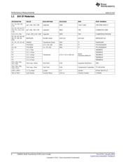
1.1 Bill Of Materials .................................................................................................... 6
1.2 Performance Characteristics (Push-Pull Converters with Non-Regulated Outputs) ...................... 7
List of Figures
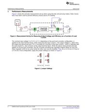
1 Measurement Set-Up for Measuring Output Voltage and Efficiency as a Function of Load Current ............ 2
2 Jumper Settings............................................................................................................. 2
3 SN6501 EVM Schematic................................................................................................... 3
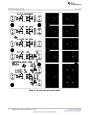
4 Top Layer (Left) and Layer 2 (Right)..................................................................................... 4
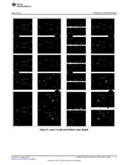
5 Layer 3 (Left) and Bottom Layer (Right) ................................................................................. 5
6 Output Voltage Versus Load Current Vin = 3.3 V, Vout = 3.3 V...................................................... 7
7 Efficiency Versus Load Current Vin = 3.3 V, Vout = 3.3 V ............................................................ 7
8 Output Voltage Versus Load Current Vin = 5 V, Vout = 5 V .......................................................... 7
9 Efficiency Versus Load Current Vin = 5 V, Vout = 5 V................................................................. 7
10 Output Voltage Versus Load Current Vin = 3.3 V, Vout = 5 V........................................................ 7
11 Efficiency Versus Load Current Vin = 3.3 V, Vout = 5 V .............................................................. 7
12 Output Voltage Versus Load Current Vin = 3.3 V, Vout = 5 V........................................................ 8
13 Efficiency Versus Load Current Vin = 3.3 V, Vout = 5 V .............................................................. 8
14 Output Voltage Versus Load Current Vin = 3.3 V, Vout = 3.3 V...................................................... 8
15 Efficiency Versus Load Current Vin = 3.3 V, Vout = 3.3 V ............................................................ 8
16 Output Voltage Versus Load Current Vin = 5 V, Vout = 5 V .......................................................... 8
17 Efficiency Versus Load Current Vin = 5 V, Vout = 5 V................................................................. 8
1
SLLU174–January 2013 SN6501 Multi-Transformer EVM User’s Guide
Submit Documentation Feedback
Copyright © 2013, Texas Instruments Incorporated


