


下载

Rev 0.4 11/14 Copyright © 2014 by Silicon Laboratories AN692
AN692
Si4355/Si4455 PROGRAMMING GUIDE
1. Introduction
This document provides an overview of how to configure and control the following EZRadio
®
chips:
Si4455 transceiver
Si4355 receiver
The following code examples are covered in this programming guide:
How to set up a continuous wave (CW) transmission.
How to set up a pseudo random (PN9) transmission.
How to transmit in TX direct mode.
How to receive in RX direct mode (for BER measurement).
How to transmit a simple packet in Packet Handler mode.
How to receive a simple packet in Packet Handler mode.
How to implement bidirectional variable length packet based communication.
2. Hardware Options
The source code is provided for two different hardware platforms:
RFStick
Wireless Motherboard + RF Pico Board
A separate Silicon Labs IDE workspace is provided for each example on the two platforms.
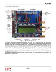
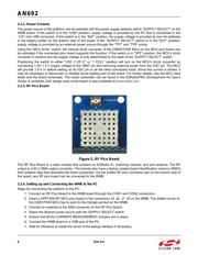
2.1. The RFStick Platform
Figure 1. RFStick
The RFStick is a basic demo system for the evaluation of the EZRadio chips. The board has two main parts, the
MCU part and the radio part. The MCU part of the board contains a Silicon Labs C8051F930 MCU and basic
human interface devices (four push-buttons, four LEDs, four switches and a buzzer). The radio part contains the
EZRadio chip, the matching circuit, and the antenna. The RF output is selectable via a 0 resistor between a PCB
antenna and an optional (unpopulated) 50 SMA output connector. The MCU is connected to the EZRadio chip
via an SPI bus and some other GPIOs (see Table 1). The RF section of the board can be broken off along a
perforation between the two rows of J3 and installed in the user’s own hardware as a radio module by utilizing the
remaining row of J3.
Table 1 contains the signal connections between the EZRadio chip and the MCU: