
下载
Maxim > Design Support > Technical Documents > Reference Designs > Automotive > APP 2081
Maxim > Design Support > Technical Documents > Reference Designs > Filter Circuits (Analog) > APP 2081
Maxim > Design Support > Technical Documents > Reference Designs > Signal Generation Circuits > APP 2081
Keywords: digitally controlled sine-wave generator, sine wave, circuits, IC3
REFERENCE DESIGN 2081 INCLUDES: Tested Circuit Schematic Description
Digitally Controlled Sine-Wave Generator
Jun 27, 2003
A similar version of this article appeared in the May 15, 2003 issue of EDN magazine.
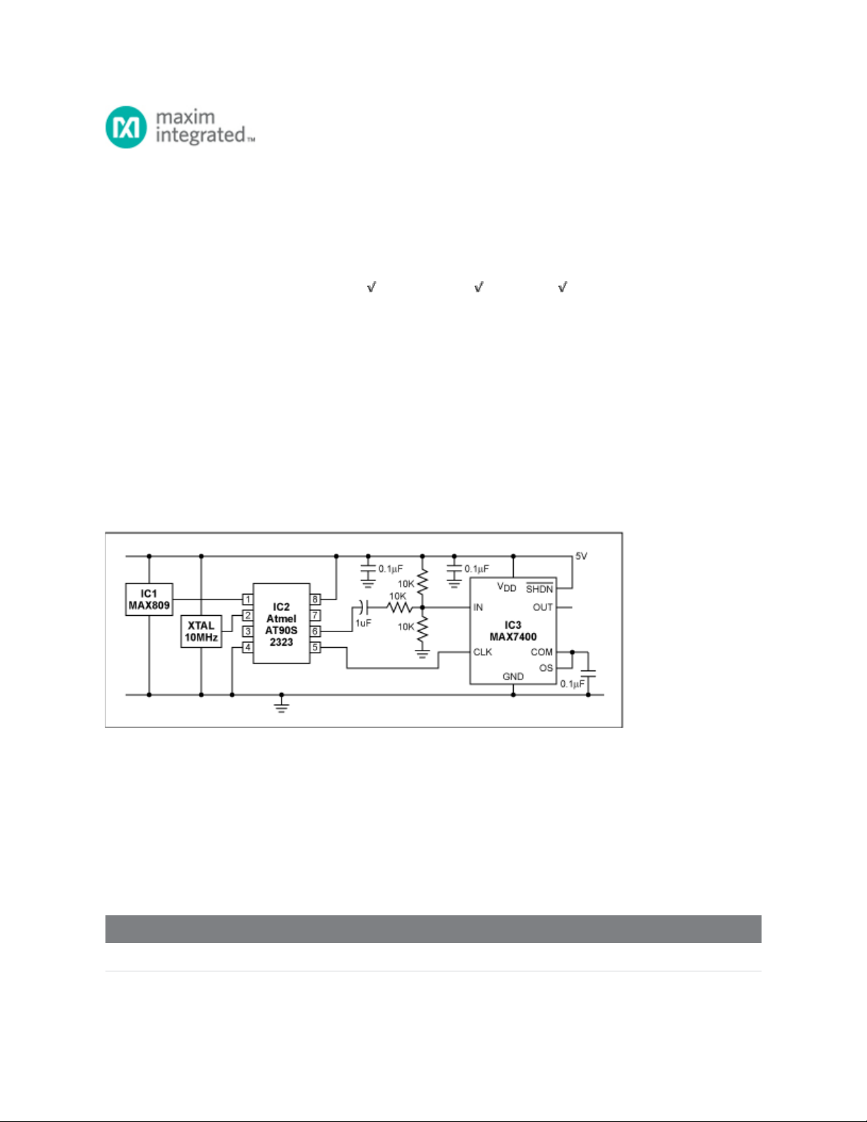
The circuit of Figure 1 produces an accurate variable-frequency sine wave for use as a general-purpose
reference signal. It includes an 8th-order elliptic, switched-capacitor lowpass filter (IC3) that is clocked
with a 100kHz square wave generated by microcontroller IC2. (Any other convenient squarewave source
is also acceptable.) The microcontroller is clocked by a 10MHz oscillator module. A voltage supervisor
(IC1) ensures correct operation in the event of a power failure. IC3 sets the filter's cutoff frequency at
1/100 the clock frequency.
Figure 1. By removing harmonics from a square wave, this circuit generates an accurate and adjustable
sine-wave output.
The 8th-order elliptic filter's sharp rolloff sharply reduces the harmonic amplitudes in a 1kHz square-
wave input, thereby producing a near-perfect 1kHz sine wave at its output. Using divider-chain logic or a
processor, you can then create a digitally adjustable sine-wave source by adjusting the clock and input
frequencies while maintaining a ratio of 100:1 between them.
To prevent clipping at the positive and negative peaks, attenuate the input signal and superimpose it on
a dc level of V
CC
/2. The result (for a 5V input) is a 2.25V peak-to-peak output.
Related Parts
MAX7400 8th-Order, Lowpass, Elliptic, Switched-Capacitor Filters Free Samples
MAX809 3-Pin Microprocessor Reset Circuits Free Samples
Page 1 of 2