


下载

More Information
- Wireless Home
- Application
Notes and Tutorials
- EV Kit Software
- Technical Support
Click here for an overview of the wireless
components used in a typical radio
transceiver.
Maxim > Design Support > Technical Documents > Reference Designs > Microcontrollers > APP 5404
Maxim > Design Support > Technical Documents > Reference Designs > Wireless and RF > APP 5404
Keywords: wireless automatic meter reading, AMR, water meter, transceiver, transmitter, receiver, ISM, RF, PCB, layout, schematic, hardware,
firmware, microcontroller, utility company, smart grid, protocol, antenna, link, range
REFERENCE DESIGN 5404 INCLUDES: Tested Circuit Schematic BOM Board Available Description Test Data Software Layout
LFRD003: Water Meter Automatic Meter Reading (AMR) Reference
Design
By: Martin Stoehr, Principal Member of the Technical Staff, Applications
May 11, 2012
Abstract:
This reference
design provides a complete demonstration platform for using industrial/scientific/medical
radio frequency (ISM-RF) products in an automatic meter reading (AMR) application. This document includes the
hardware, firmware, and system structure requirements for implementing an AMR design that demonstrates
operation with a physical water meter.
General Description
The MAX7032 transceiver reference design (RD) is a self-contained evaluation platform for exercising the
device as a wireless automatic meter reading (AMR) and water meter demo system. With the use of the
Maxim USB-to-JTAG board (MAXQJTAG-USB), the MAXQ610 on both the handheld interface (HHI) unit and
the various meter (MTR) radio modules can be programmed by the end user.
The meter board enables basic human interaction through a single momentary switch input and an LED for
visual feedback. The MTR is designed to be compact, providing a self-contained transceiver board with a
radio, microcontroller, and multiple "ports" for connecting various meter inputs to the system. Two separate
designs are provided: one with an MMCX antenna connection, and the other with a small-footprint antenna-mounting option. Input to the MTR
system can be configured with up to six ports, and the primary input interfaces with a "pulse" or dry contact (reed) output meter. This board can
be operated from any 3V power source (1.7V to 3.6V for the MAXQ610, 2.1V to 3.6V for the MAX7032).
The HHI board has seven menu keys for user input, a reset switch, a 102 pixel x 64 pixel LCD display with multicolor LED backlighting for menu
interactions, plus a receive signal indicator (RSI) LED. The shape of the HHI fits within a Series 55 BOX enclosure, and has a high-density
connector for interfacing with an RF module.
Both systems are preprogrammed with operational firmware to demonstrate a simple wireless AMR meter (slave)/reader (master) system. Gerber
files are available for simple cut-and-paste designs of the radio sections or the full implementation.
Features
Proven printed circuit board (PCB) layout
Proven component parts list
Preprogrammed transceiver (TRX) pair for quick demonstration capabilities
Free MAXQ® microcontroller programming tools available for flexible operation
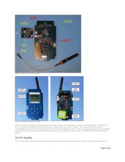
The Handheld Interface (HHI)
The HHI is a two-part system that comprises a human interface board, which contains a LCD display, a key encoder, and a microcontroller. This
HHI is mated to an RF module to form a complete handheld communication system. The Phase I design interfaces to a MAX7032 transceiver
module through a 10-pin, high-density connector. The Phase III design and the RF modules described later interface through a 60-pin connector.
The HHI board provides a basic method of input with seven keys and one reset switch. This interface provides for flexible output through an
Electronic Assembly DOGS102-6, 102 pixel x 64 pixel, transflective LCD display with a duo-color backlight. The board also contains an
independent "signal" LED.
This system interfaces with the RF module through a board-to-board, mezzanine connector using a firmware-defined SPI. The MCU is
programmed through an edge connector interface to USB. The power can be supplied through either the edge connector or a wired battery
connection. The RF module has an MMCX connector, to which a 6" cable and a reduced-height Linx antenna may be attached, providing a small
form factor assembly. The entire system has been designed to fit within a box enclosure, conveniently sized for handheld use (Figure 1).
Page 1 of 29