
下载
Maxim > Design Support > Technical Documents > Reference Designs > Circuit Protection > APP 3984
Maxim > Design Support > Technical Documents > Reference Designs > Hot-Swap and Power Switching Circuits > APP 3984
Keywords: FireWire,IEEE-1394,UL,UL-recognized,MAX5943A,MAX5944,protective,protection,protective-circuit
REFERENCE DESIGN 3984 INCLUDES: Tested Circuit Schematic BOM Description Test Data Layout
UL Recognized, IEEE 1394 Single- and Dual-Port
FireWire Protective Circuits
Feb 08, 2007
Abstract:
This application note
describes Maxim's UL® Recognized, IEEE® 1394™, single- and dual-port FireWire®
protective circuits. The single-port FireWire protective circuit is designed using the MAX5943A, while the dual-port
FireWire protective circuit utilizes the MAX5944. To assist designers with implementing these circuits, this
application note details the schematics, PCB layout, and bill of materials for each UL Recognized circuit.
Introduction
After extensive safety testing, the MAX5943A single-port and MAX5944 dual-port FireWire current limiter and low-
drop ORing switch controllers have been UL Recognized under the Component Recognition Program of
Underwriters Laboratories, Inc.® Note that the circuits themselves, not any individual component thereof, have been
UL Recognized. To assist designers with implementing these UL Recognized circuits, this application note provides
schematics for each circuit. It also provides the bill of materials (BOM) for each of the two circuits, detailing therein
the components required for UL Recognition. Any changes to the basic circuit, or changes to the current-carrying
components (the sense resistor or MOSFET switches) of the circuits, would necessitate additional UL testing to
achieve UL Recognition. However, increasing the Ohmic value of the sense resistor to decrease the current-limit
value is not expected to require additional safety testing.
Neither of these circuits requires a series fuse to achieve the UL's safety specifications, which require safe
operation in the event of a single-element failure (open or short circuit) between any two of the three MOSFET or
BJT terminals. These circuits meet the UL's safety requirements by employing two MOSFETs placed in series such
that one of the two MOSFETs is able to sustain a short circuit from source to drain without compromising the safety
of the complete circuit. A network of four resistors and two pnp transistors are placed between the MOSFET gates
and the controller IC to isolate and drive the two individual MOSFETs from the single gate-control signal (per
channel in the two-port circuit) from the controller IC. UL testing was performed with a 12V power source.
Circuit Description
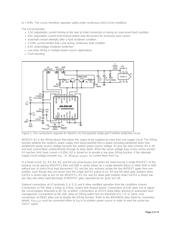
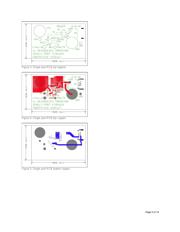
Figure 1 illustrates a single-port FireWire protective circuit implemented with the MAX5943A. Input power of 7.5V to
37V is applied at the input V
IN
, and a load is connected from pin 1 to pin 2 of the 6-pin IEEE 1394 connector at the
output. Load current flowing through sense-resistor R2 generates the current-sense voltage applied from pin 16 to
pin 15 of the MAX5943A controller IC. When this sensed voltage reaches a 50mV ±5% threshold level, the output
current is regulated to maintain a constant sensed voltage. If the regulated current continues beyond 2ms, the
controller automatically disconnects the load, although the current can continue indefinitely at any value below the
50mV threshold.
Under steady-state conditions, GATE2 is driven ≈5.5V higher than V
IN
to enhance MOSFET N2. When output
current reaches the limiting value, the voltage at GATE2 drops to maintain current at the set point until the current-
limit timeout occurs, or until the output current drops below the set point. Upon load disconnect, the GATE2 voltage
drops quickly to zero, the fault signal is set, and the controller waits for 256ms before attempting a restart. If an
overload still exists, the timeout and automatic restart will continue indefinitely, setting the current-limited duty cycle
Page 1 of 14