

下载
Maxim Integrated Page 1 of 9
MAX1720x/MAX1721x Battery Pack
Implementation Guide
UG6258; Rev 0; 2/16
Description
This guide provides the instructions for designing the PCB and programming the
MAX17201/MAX17211/ MAX17205/MAX17215 for use in battery packs. Proper circuit board layout is
critical for measurement accuracy and ESD ruggedness. This application note is a guide for achieving
the highest performance possible given limited board size and component position flexibility.
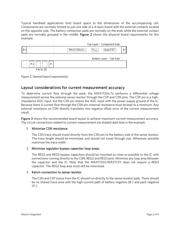
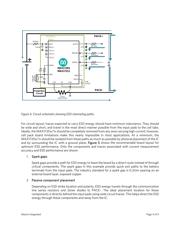
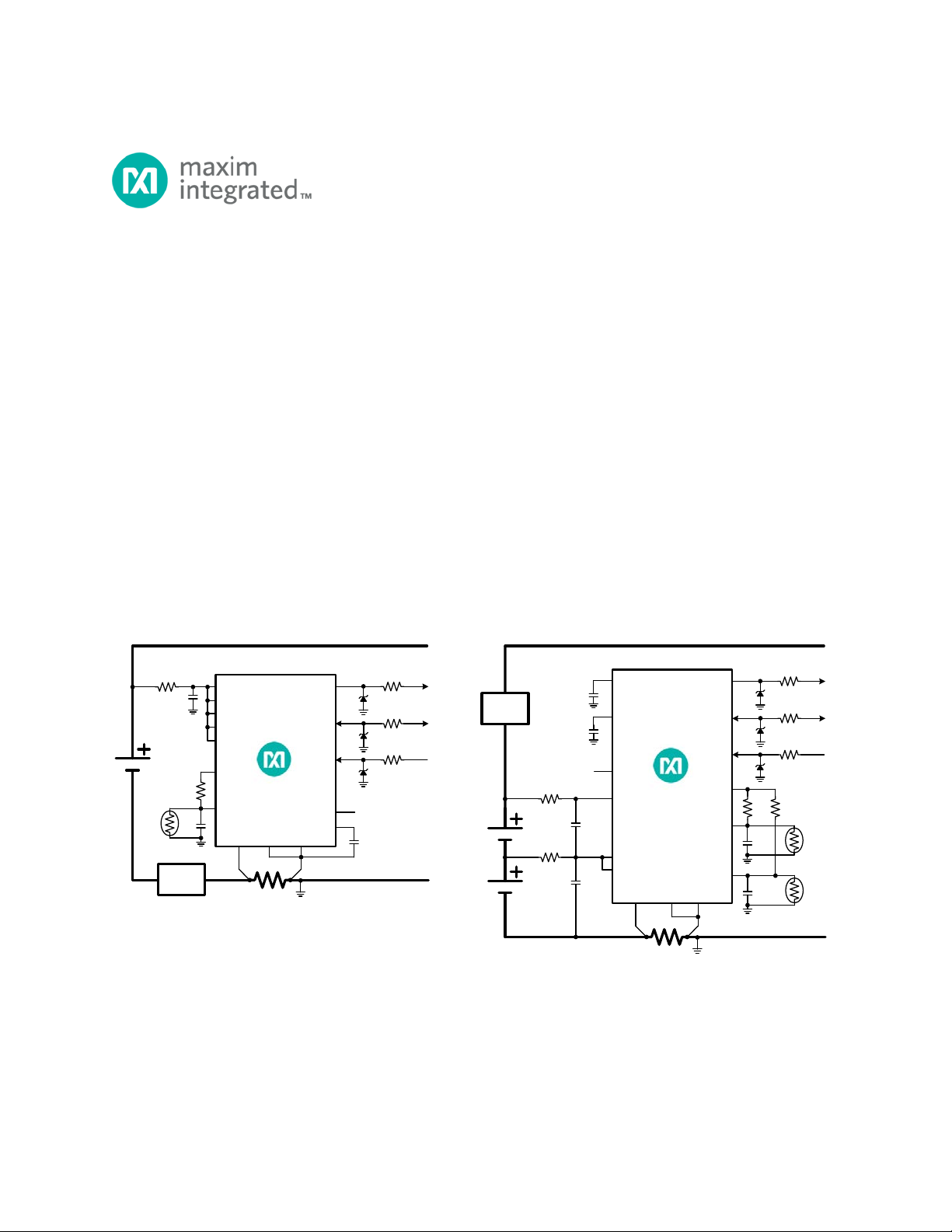
Figure 1
shows a single-cell (MAX17201/MAX17211) and a multi-cell (MAX17205/MAX17215) circuit
configuration. Note that other circuit configurations for this IC are possible, and should follow the same
layout guidelines. This guide also includes a recommended board level production test procedure
requiring minimum test time.
50 Ohm
1nF
OD/SCL
DQ/SDA
ALRT1
CSP
BATT
CSN
AIN1
THRM
10nF
PACK+
PACK
-
150 Ohm
150 Ohm
4.
7V
4
.7V
MAX17205
MAX17215
1.8V
REG2
0.
47uF
10K
Ohm
10K NTC
1
K Ohm
4
.7V
CELL2
CELL1
Protection
Circuit
R
SENSE
0.010 Ohms
EP
3.
4V
REG3
0.47uF
AIN2
10nF
10K NTC
10K
Ohm
2
S BALANCING CONFIGURATION WITH HIGH SIDE PROTECTOR
CELLx
50 Ohm
1nF
10 Ohm
0.
47uF
OD/SCL
DQ
/SDA
ALRT1
CSP
BATT
CSN
AIN1
THRM
10nF
PACK
+
PACK-
150 Ohm
150 Ohm
4.7V
4.7
V
MAX
17201
MAX17211
REG3
1
.8V
REG
2
0.47uF
10K
Ohm
10K NTC
1K Ohm
4.7V
CELLx
CELL2
CELL1
Protection
Circuit
R
SENSE
0.010 Ohms
AIN2
EP
1S CONFIGURATION WITH LOW SIDE PROTECTOR
nPackCFG=0x1C01
nPackCFG=
0x3C22
Figure 1. Single-cell and multi-cell circuit schematics.