

下载

Application Note 117
AN117-1
an117f
April 2008
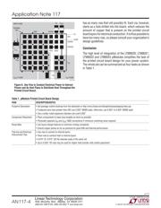
The LTM80xx series of μModules have both I/O and power
connections. The I/O connections are typically routed with
a trace. The power and ground connections are usually
hooked up by laying planes. If the μModule footprint uses
a solder mask expansion of zero, all of the pads will be the
same size. If the solder mask expansion is greater than
zero, the power pads will be bigger than the I/O pads.
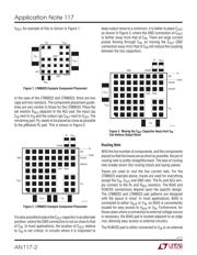
Take a moment to examine the pad pattern. Note that the
pads surrounding the V
IN
net have been depopulated.
The reason for this is because each of the LTM8020,
LTM8021, LTM8022 and LTM8023 μModules are rated
for 36V
DC
operation. According to IPC 2221, Generic
Standard on Printed Board Design, Table 6-1, uncoated
external printed circuit board conductors, such as solder
pads, with 31 to 50V between them must be separated
by at least 0.6mm, or 0.0236”. On the LTM80xx series of
μModules, the square pads are 0.025” on a side, placed at
a 0.050” pitch. If the μModule operates above 31V steady
state, the actual printed circuit board pad may not exceed
0.0257” before violating the IPC-2221 standard. In this
case, it is best to make the footprint pad opening 0.025”
NMSD with a zero solder mask expansion. If no adjacent
pins operate above 30V, any size pad with a net opening
between 0.025” and 0.029” will suffi ce.
Component Placement
In general, components should be placed which result in
traces that are as short as possible. There are very few
components to put down, and are located near the edge
of the device, which simplifi es the design. For example,
on the LTM8020, the typical components are the μModule,
a single output voltage resistor, along with an input and
output cap. In order to keep the traces as short as possible,
place the set resistor R
ADJ
adjacent to the ADJ pad, the
input cap C
IN
next to V
IN
and the output cap C
OUT
next to
The LTM8020, LTM8021, LTM8022 and LTM8023 μModules
are complete easy-to-use encapsulated step down DC/DC
regulators intended to take the pain and aggravation out
of implementing a switching power supply onto a system
board. With a μModule, you only need an input cap, output
cap and one or two resistors to complete the design. As
one might imagine, this high level of integration greatly
simplifi es the task of printed circuit board design, reduc-
ing the effort to four categories: component footprint
generation, component placement, routing the nets, and
thermal vias.
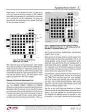
Component Footprint Generation
One of the fi rst things to do when designing a printed
circuit board is generate the footprint or decal for each
component. The components required to complete the
LTM8020, LTM8021, LTM8022 and LTM8023 designs
are common resistors and capacitors that have industry
standard footprints. The basic information necessary to
generate the footprint for a LTM8020, LTM8021, LTM8022
or LTM8023 is given in the package outline drawing, which
can be found in the “Package Description” section of the
data sheet, which is also accessible online at:
http://www.linear.com/designtools/packaging/index.jsp
It is indexed by package drawing number, which is also
found in the “Package Description” section of the data
sheet.
Next, choose a pad size in accordance with Linear Tech-
nology Application Note 100. For the LTM8020, LTM8021,
LTM8022, and LTM8023, square pads with sides measuring
between 0.025” and 0.029” will work for most applications.
Per the recommendations of the application note, make
the pads non-solder mask defi ned (NMSD), with a solder
mask expansion of zero to 0.002”, or 0.05mm.
DC/DC µModule Regulator Printed Circuit Board
Design Guidelines
(LTM802x Series are used for this discussion)
By David Ng
L, LT, LTC and LTM are registered trademarks of Linear Technology Corporation.
All other trademarks are the property of their respective owners.