

下载

User's Guide
SLVU895A–March 2013–Revised June 2013
LMZ31710, LMZ31707 and LMZ31704
Simple Switcher® Power Module Evaluation Module
The LMZ31710EVM-001, LMZ31707EVM-002 and LMZ31704EVM-003 evaluation modules are designed
as an easy-to-use platform that facilitates an extensive evaluation of the features and performance of the
Simple Switcher® power module. This guide provides information on the correct usage of the EVM and an
explanation of the numerous test points on the board.
Contents
1 Description ................................................................................................................... 2
2 Getting Started .............................................................................................................. 2
3 Test Point Descriptions ..................................................................................................... 3
4 Operation Notes ............................................................................................................. 4
5 Performance Data ........................................................................................................... 4
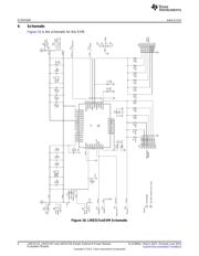
6 Schematic .................................................................................................................... 6
7 Bill of Materials .............................................................................................................. 7
8 PCB Layout .................................................................................................................. 9
List of Figures
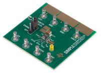
1 LMZ317xxEVM User Interface ............................................................................................ 2
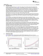
2 LMZ31710EVM Efficiency ................................................................................................. 4
3 LMZ31710EVM Power Dissipation ....................................................................................... 4
4 LMZ31710EVM Load Regulation ......................................................................................... 4
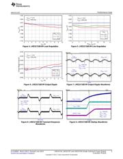
5 LMZ31710EVM Line Regulation .......................................................................................... 4
6 LMZ31710EVM Output Ripple ............................................................................................ 5
7 LMZ31710EVM Output Ripple Waveforms.............................................................................. 5
8 LMZ31710EVM Transient Response Waveforms ...................................................................... 5
9 LMZ31710EVM Startup Waveforms...................................................................................... 5
10 LMZ317xxEVM Schematic................................................................................................. 6
11 LMZ317xxEVM Topside Component Layout............................................................................ 9
12 LMZ317xxEVM Bottom-Side Component Layout....................................................................... 9
13 LMZ317xxEVM Layer 1 Copper......................................................................................... 10
14 LMZ317xxEVM Layer 2 Copper......................................................................................... 10
15 LMZ317xxEVM Layer 3 Copper......................................................................................... 11
16 LMZ317xxEVM Layer 4 Copper......................................................................................... 11
List of Tables
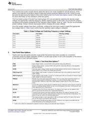
1 Output Voltage and Switching Frequency Jumper Settings........................................................... 3
2 Test Point Descriptions..................................................................................................... 3
3 LMZ317xxEVM Bill of Materials........................................................................................... 7
1
SLVU895A–March 2013–Revised June 2013 LMZ31710, LMZ31707 and LMZ31704 Simple Switcher® Power Module
Evaluation Module
Submit Documentation Feedback
Copyright © 2013, Texas Instruments Incorporated