
下载

User's Guide
SLVUAA1–September 2014
Evaluation Module for LM5069EVM-627 with Surge
Stopper and Reverse Voltage Protection
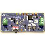
This user’s guide describes the evaluation module (EVM) for the LM5069. The LM5069 is a positive high
voltage hotswap/inrush current controller with power limiting.
Contents
1 Introduction ................................................................................................................... 2
1.1 Features.............................................................................................................. 2
1.2 Applications.......................................................................................................... 2
2 Board Description............................................................................................................ 3
3 Theory of Operation ......................................................................................................... 3
4 Board Connection/Setup and Probe Cautions........................................................................... 4
5 Circuit Parameter Changes................................................................................................. 5
5.1 Current Limit......................................................................................................... 5
5.2 Power Limit .......................................................................................................... 5
5.3 Insertion Time ....................................................................................................... 5
5.4 Fault Detection and Restart ....................................................................................... 5
5.5 UVLO/OVLO Input Voltage Thresholds.......................................................................... 6
5.6 Surge Clamping..................................................................................................... 9
5.7 Shutdown ............................................................................................................ 9
5.8 Power Good Output............................................................................................... 10
5.9 Reverse Hookup Protection...................................................................................... 10
6 Performance Characteristics Plots....................................................................................... 10
6.1 Reverse Polarity Input ............................................................................................ 10
6.2 Insertion Time Delay.............................................................................................. 11
6.3 Fault Timeout ...................................................................................................... 11
6.4 Restart Timing ..................................................................................................... 12
6.5 Turn-on Sequence with No Load Current...................................................................... 12
6.6 Turn-on Sequence with 1-A Load Current ..................................................................... 13
6.7 Output Shutdown Using UVLO Pin ............................................................................. 13
6.8 Input Surge......................................................................................................... 14
6.9 Inrush Current ..................................................................................................... 15
7 Schematic ................................................................................................................... 17
8 PCB Layout ................................................................................................................. 18
9 Bill of Materials (BOM)..................................................................................................... 20
List of Figures
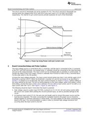
1 Power Up Using Power Limit and Current Limit ......................................................................... 4
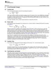
2 Fault Timeout and Restart Sequence..................................................................................... 6
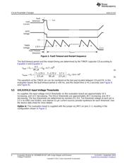
3 UVLO, OVLO Inputs (Option A)............................................................................................ 7
4 UVLO, OVLO Inputs (Option B)............................................................................................ 8
5 Minimum UVLO Threshold, Adjustable OVLO........................................................................... 9
6 Reverse Polarity Input ..................................................................................................... 10
7 Insertion Timer Delay...................................................................................................... 11
8 Fault Timeout ............................................................................................................... 11
9 Restart Timing .............................................................................................................. 12
1
SLVUAA1–September 2014 Evaluation Module for LM5069EVM-627 with Surge Stopper and Reverse
Voltage Protection
Submit Documentation Feedback
Copyright © 2014, Texas Instruments Incorporated