


下载

User's Guide
SNVA074A–May 2004–Revised May 2013
AN-1299 LM5041 Evaluation Board
1 Introduction
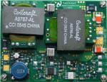
The LM5041 evaluation board is designed to provide the design engineer with a fully functional current fed
push-pull power converter to evaluate the LM5041 controller, and also the LM5101 buck stage gate driver,
in a typical environment. Another name often used for the current fed push-pull is a “Cascaded” topology.
The performance of the evaluation board is as follows:
• Input range: 35V to 80V
• Output voltage: 2.5V
• Output current: 0 to 50A
• Measured efficiency: 89% at 50A, 91% at 20A
• Board size: 2.3 × 3.0 × 0.5 inches
• Load Regulation: 0.1%
• Line Regulation: 0.1%
• Line UVLO, Current Limit
The printed circuit board consists of 4 layers of 3 ounce copper on FR4 material with a total thickness of
0.050 inches. Soldermask has been omitted from some areas to facilitate cooling. The unit is designed for
continuous operation at rated load at < 40°C and a minimum airflow of 200 CFM.
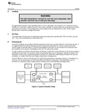
2 Theory of Operation
The current fed push-pull converter is a buck type converter consisting of a buck regulation stage followed
by (cascaded by) a push-pull isolation stage that also provides voltage reduction in the transformer. The
buck stage is synchronous, the upper and lower MOSFETS are both N-channel, which are driven by the
LM5101 high voltage buck stage driver. The signals to the driver are provided by the LM5041, which
drives the push-pull stage directly.
The push-pull stage is fed directly from the buck inductor current. The push-pull duty cycles actually
overlap slightly so that there is always a current path for the buck inductor. One cycle of the buck regulator
is provided for each of the push and pull switching events providing proper flux balance in the transformer.
Operating the transformer with both primary windings active during the brief overlap time does not present
a problem to either the current source or the transformer. When both windings are active the
magnetomotive force of the transformer breaks down and the impedance at the VPP node decreases
toward zero. At that time, the inductor source current divides evenly between the primary windings. Some
losses are avoided in the current fed push-pull topology since switching losses require the presence of
both voltage and current.
The output stage uses synchronous rectification to avoid consuming a large percentage of the 2.5 volt
output by the forward voltage drop of a typical Schottky rectifier.
Feedback from the output is processed by an amplifier and reference and then coupled back to the
LM5041 controller through an optocoupler.
All trademarks are the property of their respective owners.
1
SNVA074A–May 2004–Revised May 2013 AN-1299 LM5041 Evaluation Board
Submit Documentation Feedback
Copyright © 2004–2013, Texas Instruments Incorporated