
下载

User's Guide
SNWA009A–March 2008–Revised April 2013
AN-1806 LMV232 Evaluation Board
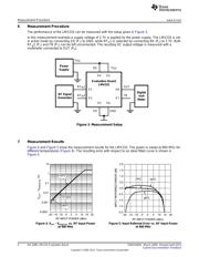
1 General Description
This board, the LMV232TLEVAL, can be used to evaluate the Texas Instruments LMV232 dual-channel
mean square power detector. The LMV232 mean square power detector is particularly suited for accurate
power measurement of RF modulated signals that exhibit large peak to average ratios, that is, large
variations of the signal envelope. Such noise-like signals are encountered in applications such as CDMA
and wideband CDMA cellphones.
2 Basic Operation
The LMV232 power detector provides an accurate power measurement for arbitrary input signals, low and
high peak-to-average ratios and crest factors. This is because its operation is not based on peak
detection, but on direct determination of the mean square value. The single supply, ranging from 2.5V to
3.3V, can be applied through connectors P
5
and P
6
of the evaluation board. The device has two digital
interfaces. The signal connected to P
3
(SD) puts the device in an active mode or a shutdown mode. When
SD = HIGH, the device is in shutdown, if SD = LOW the device is active. The signal connected to P
4
(BS)
selects the active RF input signal. When BS = HIGH, RF
IN
1 is active (P
1
). When BS = LOW, RF
IN
2 is
active (P
2
). The output voltage is measured through connector P
8
. Connector P
7
can be used to monitor
the voltage on the FB pin of the LMV232 when a 0Ω resistor is placed in R
2
. Further details can be found
in the Application Notes section of LMV232 Dual-Channel Integrated Mean Square Power Detector for
CDMA & WCDMA (SNWS017).
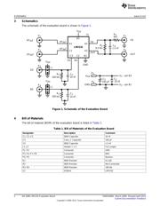
The LMV232 conversion gain and bandwidth can be configured by a resistor and a capacitor. Resistor R
1
sets the conversion gain from RF
IN
to the output voltage. A higher resistor value will result in a higher
conversion gain. The maximum dynamic range is achieved when the resistor value is as high as possible,
i.e. the output signal just doesn’t clip and the voltage stays within the baseband ADC input range. The
filter bandwidth is adjusted by capacitor C
4
. The capacitor value should be chosen such that the response
time of the device is fast enough and modulation on the RF input signal is not visible at the output (ripple
suppression). The -3 dB filter bandwidth of the output filter is determined by the time constant R
1
*C
4
.
Generally a capacitor value of 1.5 nF is a good choice.
All trademarks are the property of their respective owners.
1
SNWA009A–March 2008–Revised April 2013 AN-1806 LMV232 Evaluation Board
Submit Documentation Feedback
Copyright © 2008–2013, Texas Instruments Incorporated