
下载
1
2
5
43
V
IN
SW
FB
EN
GND
L
1
4.7 Hμ
V
OUT
C
OUT
10 Fμ
C
IN
4.7 Fμ
LM3670
V
IN
2.5V to 5.5V
C
1
C
2
R
1
R
2
1
2
5
43
V
IN
SW
FB
EN
GND
L1:10 Hμ
V
OUT
C
OUT
10 Fμ
C
IN
4.7 Fμ
LM3670
V
IN
2.5V to 5.5V
User's Guide
SNVA098D–June 2005–Revised April 2013
AN-1348 LM3670 Evaluation Board
1 Introduction
The LM3670 evaluation board is a working demonstration of a step-down DC-DC converter. This
document contains information about the evaluation board. For further information on buck converter
topology, device electrical characteristics, and component selection please refer to the data sheet.
2 General Description
The LM3670 converts high input voltages to lower output voltages with high efficiency through an inductor
based switching topology. Automatic intelligent switching between PWM low-noise and PFM low-current
mode offers improved system control. LM3670 is available in both fixed output voltage options (1.2V,
1.5V, 1.6V, 1.8V, 1.875V, 2.5V, 3.3V) and adjustable voltage options range from 0.7V to 2.5V. The
LM3670 is available in a SOT23-5 package.
3 Operating Conditions
• V
IN
range: 2.5V ≤ V
IN
≤ 5.5V
• Recommended load current: 0 mA ≤ I
OUT
≤ 350 mA
• Ambient temperature (T
A
) range: -40C to +85C
• Junction temperature (T
J
) range: -40C to +125C
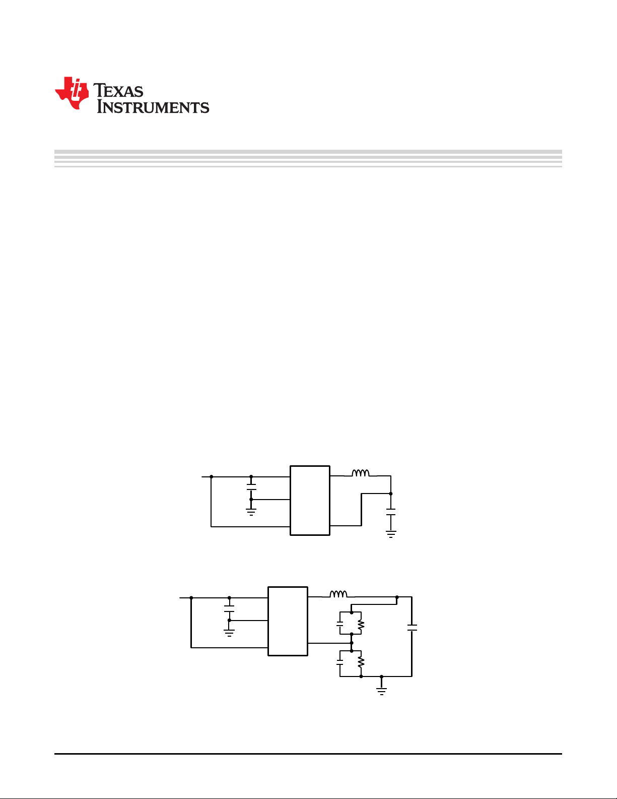
4 Typical Application
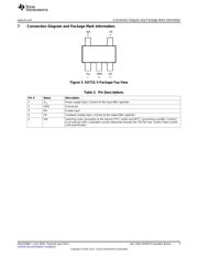
Figure 1. Fixed Output Voltage--Typical Application Circuit
Figure 2. Adjustable Output Voltage—Typical Application Circuit
All trademarks are the property of their respective owners.
1
SNVA098D–June 2005–Revised April 2013 AN-1348 LM3670 Evaluation Board
Submit Documentation Feedback
Copyright © 2005–2013, Texas Instruments Incorporated