
下载
User's Guide
SNVA102A–October 2005–Revised April 2013
AN —1356 LM2743 Evaluation Board
1 Introduction
This application notes describes the LM2743 printed circuit board (PCB) design and provides an example
typical application circuit. The demo board allows component design flexibility in order to demonstrate the
versatility of the LM2743 IC.
The demo board contains a voltage-mode, high-speed synchronous buck regulator controller. Though the
control sections of the IC are rated for 3 to 6V (V
CC
), the driver sections are designed to accept input
supply rails (V
IN
) as high as 14V.
The demo board design regulates to an output voltage of 1.2V at 3.5A with a switching frequency of
1MHz. Note, the demo board is optimized for a 1MHz, 14V input voltage compensation design, if another
switching frequency and input voltage is desired, please consult the LM2743 data sheet for control loop
compensation procedures. For additional design modifications refer to the Design Consideration section of
the LM2743 Low Voltage N-Channel MOSFET Synchronous Buck Regulator Controller Data Sheet
(SNVS276). The PCB is designed on two layers with 1oz. copper on a 62mil FR4 laminate.
2 Additional Footprints
A Schottky diode footprint (D1) is available in parallel to the low side MOSFET. This component can
improve efficiency, due to the lower forward drop than the low side MOSFET body diode conducting
during the anti-shoot through period. Select a Schottky diode that maintains a forward drop around 0.4 to
0.6V at the maximum load current (consult the I-V curve). In addition select the reverse breakdown
voltage to have sufficient margin above the maximum input voltage.
Footprint C13 is available for a multilayer ceramic capacitor (MLCC) connected as close as possible to the
source of the low side MOSFET and drain of the high side MOSFET. This will provide low supply
impedance to the high speed switch currents, thus minimizing the input supply noise. For example; a
MLCC is used (C13) in combination with aluminum electrolytic input filter capacitors, placed in designators
C12 and C14, because MLCC have lower impedance than electrolytics. If MLCCs are used in designators
C12 and C14 then component C13 is not necessary.
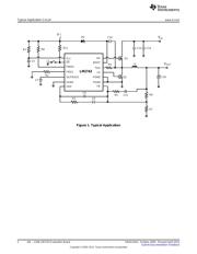
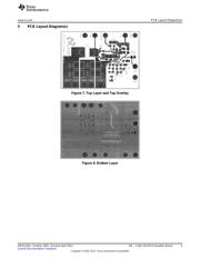
3 Typical Application Circuit
The typical application circuit in Figure 1 provides the component designators used on the demo board.
All trademarks are the property of their respective owners.
1
SNVA102A–October 2005–Revised April 2013 AN —1356 LM2743 Evaluation Board
Submit Documentation Feedback
Copyright © 2005–2013, Texas Instruments Incorporated