


下载

SJ1 SJ1
Connects Soft-
Start Capacitor
Connects Tracking
Resistors
User's Guide
SNVA244A–May 2007–Revised April 2013
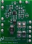
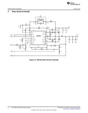
AN-1640 LM2743-19A Demo Board
1 Introduction
This user's guide describes the LM2743 printed circuit board (PCB) design and provides an example
typical application circuit. The LM2743 is a voltage mode PWM buck controller which implements
synchronous rectification. It provides a low cost, high power density, and efficient point of load solution. In
steady state operation the LM2743 is always synchronous, even at no load, thus simplifying the
compensation design. The current limit protection does not require a current limit resistor in the power
path, but is achieved by sensing the voltage V
DS
across the low side MOSFET. Though the control
sections of the IC are rated for 3 to 6V (V
CC
), the driver sections are designed to accept input supply rails
(V
IN
) as high as 16V.
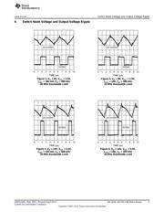
2 Specifics of the Board
This demo board targets the fixed and mobile telecommunications, industrial electronics, and distributed
power markets. The demo board has a V
IN
range of 8V to 14V and a LDO regulator, the LP2937, powers
V
CC
by regulating a 5V output voltage. The LM2743 regulates to an output range of 1.2V to 3.3V at 19A
with a switching frequency of 300 kHz. Note, the demo board is optimized for the above parameters, thus
for additional design modifications refer to the Design Consideration section of the LM2743 data sheet.
The PCB is designed on four layers, the top and bottom layers are 2oz. copper and the two inner layers
are 1oz. copper. The board measures 2.19 in. × 1.03 in. × 0.41 in. (56 mm × 26.2 mm × 10.3 mm) (l, w, h)
on a FR4 laminate.
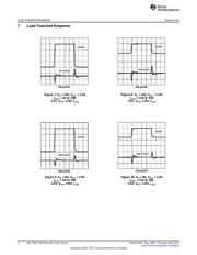
3 Feature Options
When the tracking feature of the LM2743 is required for use, remove the jumper that connects the soft-
start capacitor C10 and connect the resistor divider, on designators R13 and R14, see Figure 1. The Track
terminal has been provided for your connecting convenience. The demo board switching frequency is user
adjustable; note increasing the switching frequency results in a lower inductor current ripple and input and
output voltage ripple (if the component values are the same). Monitor the MOSFET junction temperature
since switching losses will increase, and do not exceed the maximum junction temperature of the
MOSFET. Refer to the MOSFET manufacturer datasheet for maximum junction temperature specification
and heat sinking guidelines.
Figure 1. Soft-Start and Tracking Jumper
All trademarks are the property of their respective owners.
1
SNVA244A–May 2007–Revised April 2013 AN-1640 LM2743-19A Demo Board
Submit Documentation Feedback
Copyright © 2007–2013, Texas Instruments Incorporated