

下载
C
IN
AVIN
CBOOT
SW
FB
PGOOD
RON
LM2696
V
IN
V
OUT
R
FB1
R
FB2
GND
C
OUT
R
ON
PVIN
SD
C
SS
SS
EXTV
CC
C
VCC
C
BOOT
D
SW
L
C
AVIN
C
SD
C
BY
V
PGOOD
V
SD
User's Guide
SNVA129B–October 2005–Revised April 2013
AN-1410 LM2696 Demonstration Board
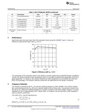
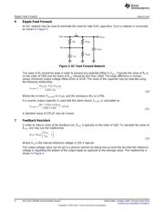
1 Introduction
The LM2696 is a constant on-time, buck regulator capable of delivering up to 3A into a load.
The LM2696 is capable of switching frequencies in the range of 100 kHz to 500 kHz and accepts input
voltages from 4.5 V to 24 V. An internal soft-start and power-good flag are also provided to allow for
simple sequencing between multiple regulators.
The operating conditions for the evaluation board are the following:
V
IN
= 6 V to 24 V
V
OUT
= 2.5 V
I
OUT
= 0A to 3A
f
SW
= 250 kHz
Figure 1. Evaluation Board Schematic
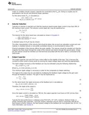
Table 1. Bill of Materials (BOM)
ID Part Number Type Size Parameters Qty Vendor
U1 LM2696 3A Constant on- HTSSOP-16 1 TI
time Regulator
L MSS1260-682MX Inductor MSS1260 6.8 µH, 4.9A ISAT 1 Coilcraft
C
IN
EEUFC1V181 Capacitor 8 x 11.5 180 µF, 35 V 1 Sanyo
C
BY
VJ0805Y104KXAM Capacitor 0805 0.1 µF 1 Vishay
C
SS
VJ080JY103KXX Capacitor 0805 0.01 µF 1 Vishay
CV
CC
VJ0805Y105JXACW1BC Capacitor 0805 1 µF 1 Vishay
C
BOOT
VJ0805Y104KXAM Capacitor 0805 0.1 µF 1 Vishay
C
AVIN
VJ0805Y105JXACW1BC Capacitor 0805 1 µF 1 Vishay
All trademarks are the property of their respective owners.
1
SNVA129B–October 2005–Revised April 2013 AN-1410 LM2696 Demonstration Board
Submit Documentation Feedback
Copyright © 2005–2013, Texas Instruments Incorporated