

下载
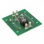
LM20242 Demonstration
Board
National Semiconductor
LM20242
CADC Design Group
November 2007
1.0 Design Specifications
Inputs Output #1
VinMin=8V Vout1=3.3V
VinMax=18V Iout1=2A
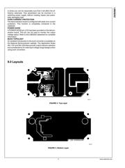
2.0 Design Description
The LM20242 demonstration board is designed to provide the
design engineer with a small, fully functional buck converter
based on Current Mode Control to evaluate the LM20242
switching regulator IC. The demonstration board provides a
3.3V output with 2A current capability. The input voltage
ranges from 8V to 18V, and is optimized for 12V. The design
operates at 300KHz, a good compromise between conver-
sion efficiency and solution size, and employs a soft-start
sequence. The printed circuit board consists of 2 layers of 2
ounce copper on FR4 material with a thickness of 0.062 inch-
es. Refer to the LM20242 datasheet for complete circuit
design information.
3.0 Features
■ Optimized for 12V to 3.3V conversion
■ 2A output current, 89% efficiency
■ 1.5% output voltage accuracy
■ 300 kHz switching frequency
■ Current Mode Control
■ Starts up into pre-biased loads
■ Soft-start set by external capacitor
■ Precision enable pin with hysteresis
■ OVP, UVLO inputs and PGOOD output
■ Internally protected with peak current limit,
shutdown and restart
■ Accurate current limit with frequency foldback
■ Input voltage range 8V to 18V
© 2007 National Semiconductor Corporation www.national.com
LM20242 Demonstration Board LM20242