

下载
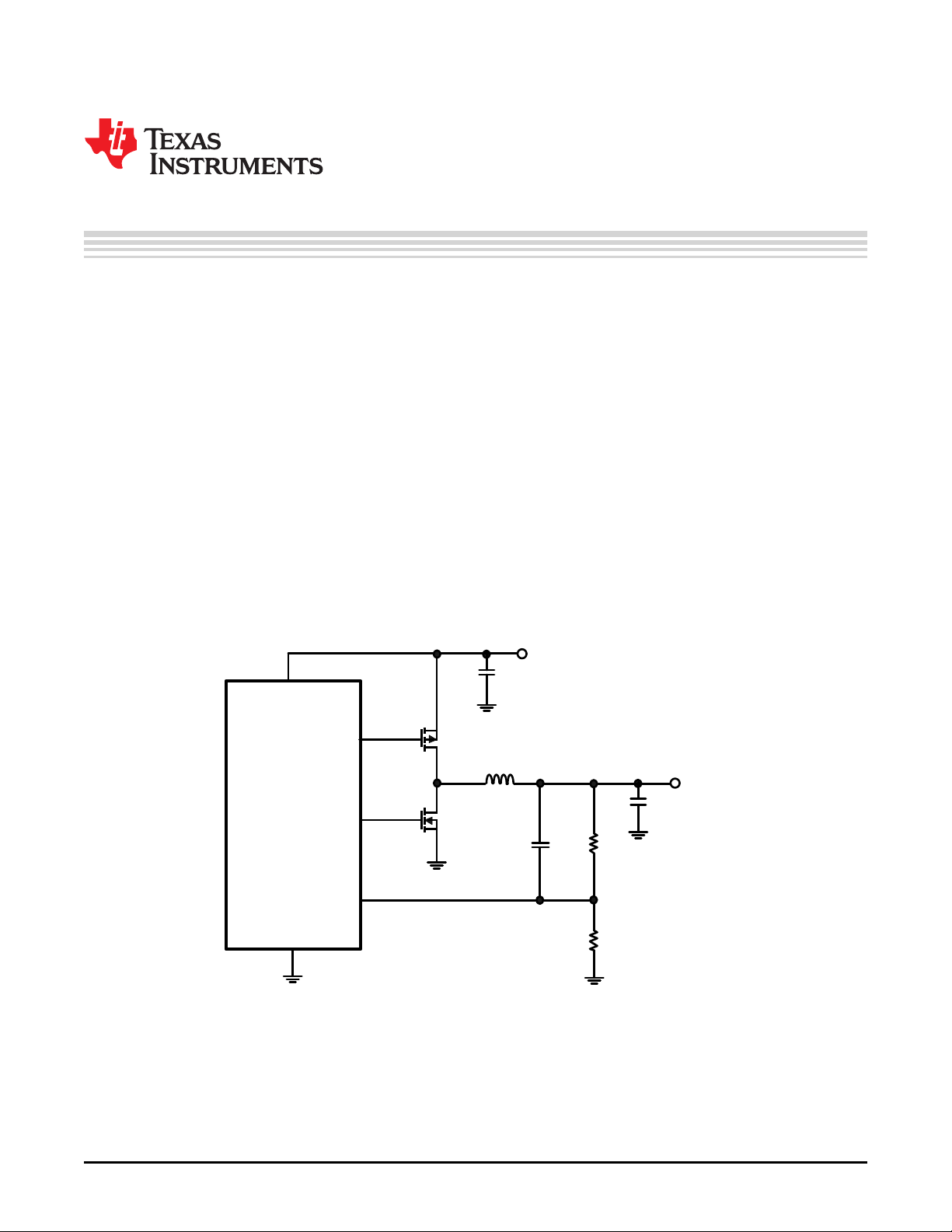
FB
V
IN
V
IN
LM1770
V
OUT
HG
LG
GND
C
OUT
Q
1
C
IN
Q
2
R
FB1
R
FB2
C
FF
L
1
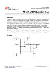
User's Guide
SNVA125B–September 2005–Revised April 2013
AN-1400 LM1770 Evaluation Board
1 Introduction
The LM1770 is a synchronous buck switching controller that is capable of accepting an input voltage in the
range of 2.8 V to 5.5 V and producing an output voltage as low as 0.8 V. By utilizing a constant on time
control scheme it allows a power supply to be designed quickly without the need for external
compensation components. The LM1770 is available in three different timing options to allow flexibility on
switching frequency and is offered in a small SOT23-5 package. These features enable a power supply to
be designed that occupies an extremely small footprint while maintaining high efficiency.
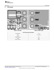
The LM1770 demo board was designed to illustrate what is possible when designing in space critical
applications. It accepts a 5 V input rail and produces a 2.5 V output. Despite the small size (the board
measures 0.7" v 0.68"), it is capable of delivering up to a maximum continuous current of 2A. At this load
the efficiency is above 92%.
For testing of the board, the input voltage can be varied over the entire operating range of 2.8 V to 5.5 V.
The timing option used for this design is the 2000 ns option (LM1770U), which sets the nominal switching
frequency to 378 kHz. Modifications can easily be made to the board to adjust the output voltage, by
changing one of the feedback resistors.
2 Schematic
All trademarks are the property of their respective owners.
1
SNVA125B–September 2005–Revised April 2013 AN-1400 LM1770 Evaluation Board
Submit Documentation Feedback
Copyright © 2005–2013, Texas Instruments Incorporated