

下载

User's Guide
SLLU186–August 2013
TLK111 Customer EVM
This user's guide details the design and operation of the evaluation module (EVM) for the TLK111.
Contents
1 TLK111 EVM Purpose and Content ...................................................................................... 1
1.1 EVM Use ............................................................................................................ 2
2 Information and Specifications ............................................................................................ 2
2.1 Usage Setup and Configuration .................................................................................. 2
2.2 Address Settings ................................................................................................... 2
2.3 TLK111CUSEVM Connections ................................................................................... 2
3 TLK111CUSEVM Specification ........................................................................................... 3
3.1 Overview ............................................................................................................ 3
3.2 Required Resources ............................................................................................... 3
3.3 Features ............................................................................................................. 3
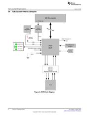
3.4 TLK111CUSEVM Block Diagram ................................................................................ 4
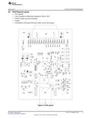
3.5 PCB Physical Layout .............................................................................................. 5
3.6 EVM Schematics ................................................................................................... 6
3.7 Bill of Materials .................................................................................................... 12
4 Software .................................................................................................................... 15
List of Figures
1 EVM Block Diagram ........................................................................................................ 4
2 EVM Layout.................................................................................................................. 5
3 TLK111CUSEVM Top Level Schematics................................................................................ 6
4 TLK111CUSEVM / TLK111 Schematics................................................................................. 7
5 TLK111CUSEVM 3.3V/1.5V LDO Schematics.......................................................................... 8
6 TLK111CUSEVM / SOR Schematics .................................................................................... 9
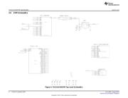
7 TLK111CUSEVM / MII Connector Schematics........................................................................ 10
8 TLK111CUSEVM / Magnetics Schematics............................................................................. 11
List of Tables
1 TLK111CUSEVM Connections............................................................................................ 2
2 TLK111CUSEVM Aneg Modes Connections............................................................................ 2
3 Bill of Materials............................................................................................................. 12
1 TLK111 EVM Purpose and Content
The Industrial Ethernet TLK111CUSEVM provides Texas Instruments customers a platform to quickly
design and market systems containing the TLK111 device. Customers are encouraged to copy EVM
components to expedite their design process. The TLK111CUSEVM operates with only a single voltage
(5V from the MII). All other voltages are internally produced.
The EVM kit contains:
• TLK111CUSEVM unit
• Printed copy of this user's guide
• TLK111CUSEVM schematic
1
SLLU186–August 2013 TLK111 Customer EVM
Submit Documentation Feedback
Copyright © 2013, Texas Instruments Incorporated