

下载
1
SLAU661–May 2016
Submit Documentation Feedback
Copyright © 2016, Texas Instruments Incorporated
ISO77xx Triple- and Quad-Digital Isolator Evaluation Module
User's Guide
SLAU661–May 2016
ISO77xx Triple- and Quad-Digital Isolator Evaluation
Module
This user’s guide describes the ISO77xx Triple- and Quad-Digital Isolator Evaluation Module (EVM). This
EVM allows designers to evaluate device performance for fast development and analysis of isolated
systems. The EVM supports evaluation of any of the TI triple- or quad-channel digital isolators in a 16-pin
SOIC (DW) package.
CAUTION
This evaluation module is made available for isolator parameter performance
evaluation only and is not intended for isolation voltage testing. To prevent
damage to the EVM, any voltage applied as a supply or digital input/output
must be maintained within the 0 V to 5.5 V recommended operating range.
Contents
1 Introduction ................................................................................................................... 2
2 Overview...................................................................................................................... 2
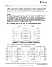
3 Pin Configurations of the ISO77xx Triple- and Quad-Channel Digital Isolators..................................... 2
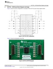
4 ISO7741 – EVM Board Block Diagram and Image...................................................................... 3
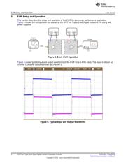
5 EVM Setup and Operation.................................................................................................. 4
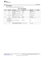
6 Bill of Materials............................................................................................................... 5
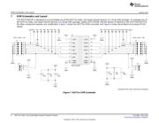
7 EVM Schematics and Layout .............................................................................................. 6
List of Figures
1 ISO773x Triple-Channel Digital Isolator Pin Configurations ........................................................... 2
2 ISO774x Quad-Channel Digital Isolator Pin Configurations............................................................ 2
3 ISO7741 EVM Configuration ............................................................................................... 3
4 ISO77xx-EVM Photograph ................................................................................................. 3
5 Basic EVM Operation ....................................................................................................... 4
6 Typical Input and Output Waveforms ..................................................................................... 4
7 ISO77xx EVM Schematic................................................................................................... 6
8 ISO77xx PCB Layout........................................................................................................ 7
List of Tables
1 Bill of Materials .............................................................................................................. 5