

下载
1
Application Note 1716
Authors: Paul Traynham and Dan Swank
Using the Transient Load Generator on the ISL8200M
2-Phase Power Module Evaluation Board
(ISL8200MEVAL2PHZ)
The Need for Testing Transient
Load Response of POL (Point of
Load) Regulators
Today’s FPGAs, DSPs and other processors require higher load
currents than in the past. It is not uncommon to see load
currents in the 10A-20A range or higher. Manufacturers of
these devices specify tight regulation of the supply even during
load transients. In order to verify the POL regulators meet
these requirements, it is necessary to test them with a load
transient generator (also referred to as a load step generator).
Load transient testing also tells us a lot about the loop
response and stability of the POL. A POL regulator may have a
stable output under a steady state load, but then exhibit large
voltage excursions, ringing, or even oscillations during a load
transient due to an under damped or unstable control loop.
The output may also be slow to respond to a load step
indicating an over damped or low bandwidth loop response.
Checking the POL regulator for these issues is a very important
step in evaluating the overall regulator performance.
A similar transient load generator is also used on many Intersil
evaluation boards including but not limited to the following
part numbers: ISL6228, ISL62391, ISL62392, ISL62386,
ISL6244, ISL6263, ISL6264, ISL6266, ISL62881, ISL62882
ISL62883, ISL62884, ISL6308, ISL6553, ISL6558, ISL6560,
ISL6562, ISL6565, ISL8102, ISL8103, ISL95210, and
ISL95870.
Limitations of Commercially
Available Electronic Loads
Commercially available electronic loads can be used to
generate steady-state load current as well as load transients.
They are easy to use and highly programmable, but have
limitations. Maximum programmable slew rates are typically
in the 1A/µs to 2A/µs range, which may be acceptable for
some lower load current applications, but can be too slow to
adequately test higher current circuits. Additionally, the slew
rates that are programmed are not the actual slew rates that
are achieved directly at the load. This is due to the inductance
limiting the di/dt in the long cabling that is typically required to
connect the electronic load to the output of the regulator.
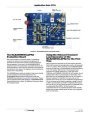
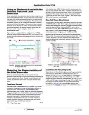
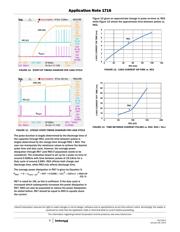
Figure 1 shows the typical setup of an electronic load applied
to the output of a POL regulator. The load is set up for a 0A-4A
step with a 4µs rise time or 1A/µs slew rate. Similarly, it is set
up for a 4A-0A step with a 4µs fall time, which also gives a
1A/µs slew rate.
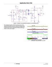
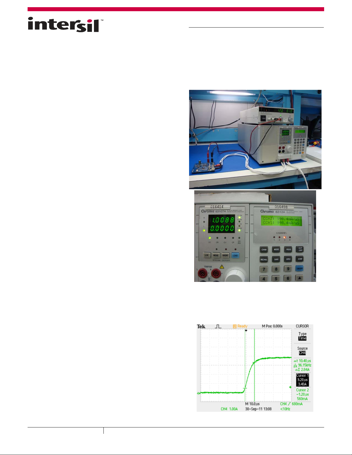
Figure 2 is a scope shot of the waveform as it appears at the
output of the regulator. Actual slew rates are reduced to
approximately 0.27A/µs (73%) primarily due to the inductance of
the cable from the electronic load to the output of the regulator.
FIGURE 1. TYPICAL ELECTRONIC LOAD SETUP
FIGURE 2. ACTUAL LOAD STEP AT LOAD
CAUTION: These devices are sensitive to electrostatic discharge; follow proper IC Handling Procedures.
Copyright Intersil Americas Inc. 2012. All Rights Reserved.
1-888-INTERSIL or 1-888-468-3774
| Intersil (and design) is a trademark owned by Intersil Corporation or one of its subsidiaries.
All other trademarks mentioned are the property of their respective owners.
January 26, 2012
AN1716.0