
下载
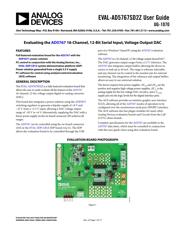
EVAL-AD5767SD2Z User Guide
UG-1070
One Technology Way • P. O. Box 9106 • Norwood, MA 02062-9106, U.S.A. • Tel: 781.329.4700 • Fax: 781.461.3113 • www.analog.com
Evaluating the AD5767 16-Channel, 12-Bit Serial Input, Voltage Output DAC
PLEASE SEE THE LAST PAGE FOR AN IMPORTANT
WARNING AND LEGAL TERMS AND CONDITIONS.
Rev. 0 | Page 1 of 17
FEATURES
Full featured evaluation board for the AD5767 with the
ADP5071 power solution
PC control in conjunction with the Analog Devices, Inc.,
EVAL-SDP-CB1Z system demonstration platform (SDP)
Power solution generated from a single 3.3 V supply
PC software for control using analysis/control/evaluation
(ACE) software
GENERAL DESCRIPTION
The EVAL -AD5767SD2Z is a fully featured evaluation board that
allows the user to easily evaluate all the features of the AD5767
16-channel, 12-bit, voltage output digital-to-analog converter
(DAC).
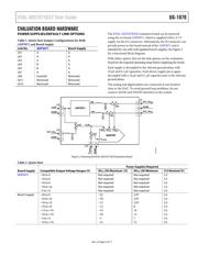
This board also integrates a power solution using the ADP5071
switching regulator to generate a bipolar supply of +8 V and
−22 V from a +3.3 V input, allowing a DAC voltage output
range of −20 V to +6 V. Alternatively, supplying the DAC with a
linear power supply via the on-board connector (J9) achieves all
ranges.
The AD5767 can be controlled using the on-board connector
(J10) or the EVA L-SDP-CB1Z SDP board (via J1). The SDP
allows the evaluation board to be controlled through the USB
port of a Windows®-based PC using the AD5767 evaluation
software.
The AD5767 is a 16-channel, 12-bit voltage output denseDAC®.
The DAC generates output ranges from a 2.5 V reference. The
AD5767 also integrates output buffers allowing the device to
source or sink up to 20 mA. The range is software selectable,
and any channel can be routed to the monitor pin for external
monitoring. The integration of the reference and output buffers
allows an easy to use universal solution.
The device requires four power supplies. AV
DD
and AV
SS
are the
positive and negative high voltage power supplies, AV
CC
is the
analog supply for the low voltage DAC circuitry, and a V
LOGIC
supply pin sets the logic levels for the digital interface pins.
The ACE software provides an intuitive graphic user interface
(GUI), allowing all of the AD5767 modes of operation to be
configured over the synchronous serial port (SPORT) interface.
The ACE software also has plugin modules for many other
Analog Devices evaluation boards and Circuits from the Lab®
(CFTL) demo boards.
Complete specifications for the AD5767 are available in the
AD5767 data sheet, which must be consulted in conjunction
with this user guide when using this evaluation board.
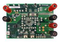
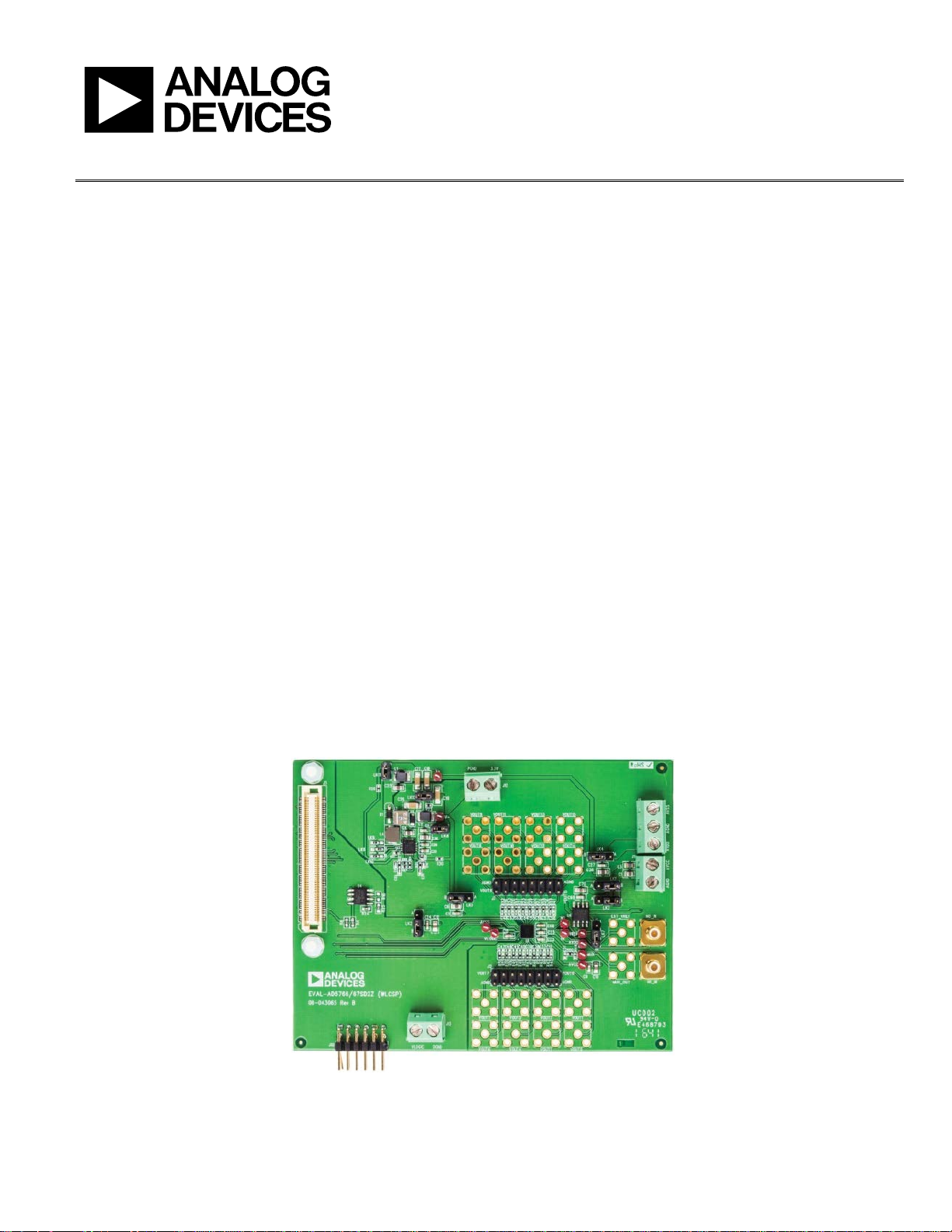
EVALUATION BOARD PHOTOGRAPH
Figure 1.
15163-001