
下载
1
®
ISL9205xEVAL1Z Evaluation Board
Application Manual
Description
The ISL9205xEVAL1Z is an evaluation tool for the ISL9205
single-cell Li-ion battery charger. The evaluation tool
provides a complete evaluation platform addressing all data
sheet specifications and functionality. The jumpers on the
board facilitate the programming of the charge current and
different charging conditions. They can also be used to make
other necessary connections, such as current measurement.
The ISL9205 is a fully integrated single-cell Li-ion battery
charger that accepts input voltages ranging from up to 6.5V.
After being powered up, the ISL9205 is capable of operating
at an input voltage as low as 2.5V. The low operating voltage
allows the charger to work with a variety of AC adapters.
The ISL9205 offers both a 3 package and pinout option and
a total of 5 functional variants. The evaluation board
accommodates all of these variants. The board provides the
pads for 2 package types: the 16 Ld package and the 10 Ld
package. On the 10 Ld package option, there are 2 pin
functions for pin 9; temperature function (TEMP) and the
remote voltage sensing (VSEN) function. Two 0Ω resistors
are used to select these functions. Please refer to the
ordering information table to order the evaluation board.
Key Features
• A Complete Evaluation Platform for the ISL9205 Charger
• Accommodates All Package Options
• Accepts Input Voltage up to 6.5V
• Flexible Power Connectors each with a Hook and a Solder
Pad Providing Variety to Users
• Convenient Jumpers for Programming the Charge
Current, Charge Mode and for Current Measurement
• 89mmx65mm Board Size Handy for Evaluation
• Six Thermal Vias in the Thermal Pad Similar To
Customers’ Thermally Enhanced Environment
• On-Board LEDs for Input FAULT
and STATUS State
Indication
What is Needed
The following instruments will be needed to perform testing:
• Power supplies:
- PS1: DC 30V/5A
- PS2: DC 20V/5A
• DC Electronic load: 20V/5A
• Multimeters
• Function generator
• Oscilloscope
• Cables and wires
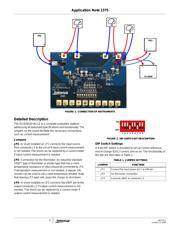
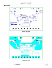
Quick Setup Guide (Refer to Figure 1)
DO NOT APPLY POWER UNTIL STEP 8
Step 1: Connect a 5V supply PS1 to J1 with the current
limit set at 1.2A
Step 2: Insert a jumper shunt between pins 2 and 3 of
J2, as shown in Figure 1
Step 3: Connect a 3.7V supply PS2 to J2 as shown in
Figure 1, with the current limit set at 1.2A
Step 4: Connect the DC electronic load of 1.2A to J2
Step 5: Connect amp-meter I2 as shown in Figure 1
Step 6: Insert a thermistor (type 103ET), or a 10k
resistor on JP2 to set a valid temperature
window
Step 7: Switch off all bits of the DIP switch except Bit 9
Step 8: Turn on Power Supplies and DC electronic load
Step 9: The green LED should be on, indicating normal
charging operation
Step 10: The current meter I2 in series with PS2 should
read about 90mA as the charging current
Step 11: Switch on Bit 5 of the DIP switch, the current
meter I2 should read about 800mA
Step 12: Switch on both Bit 5 and Bit 6; the current meter
I2 should read about 1000mA
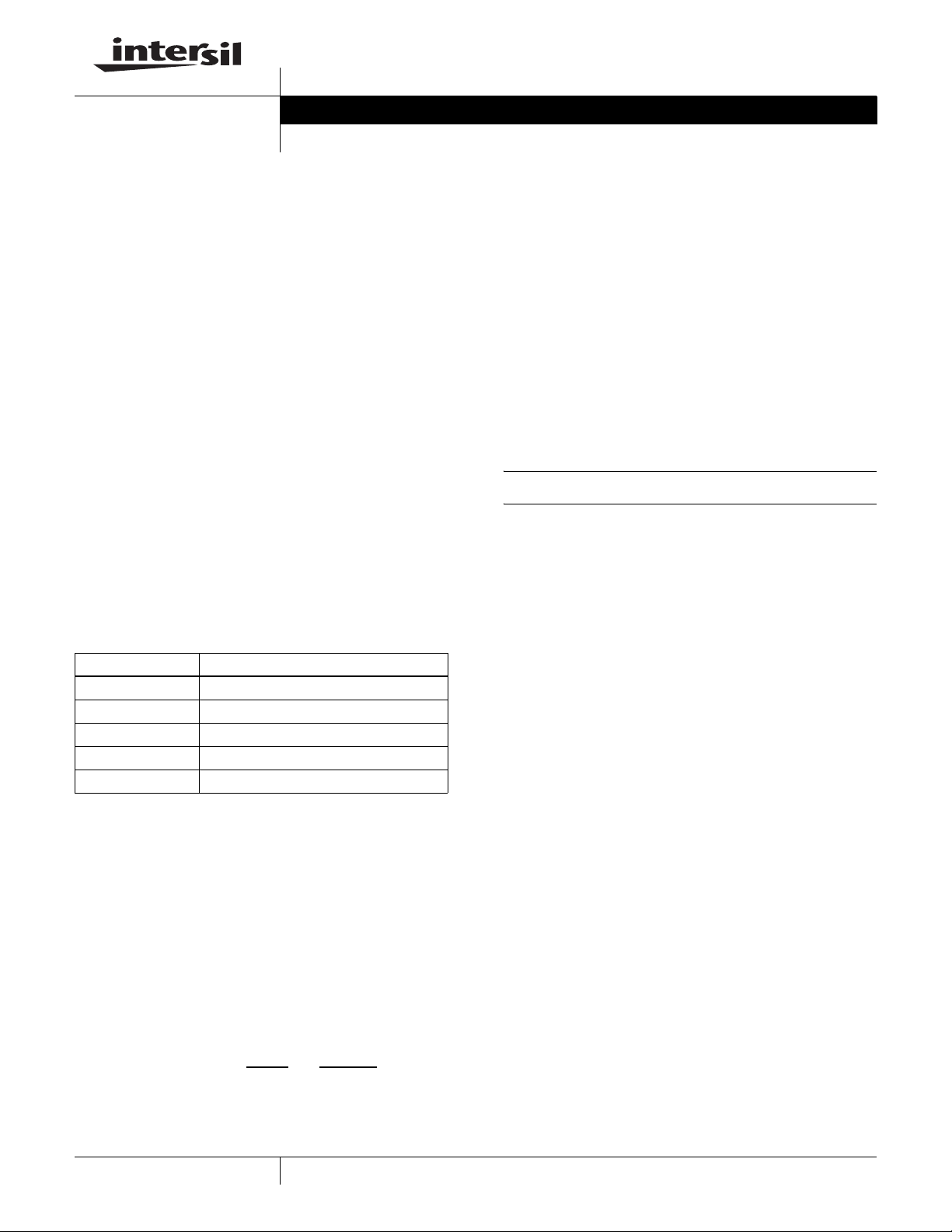
Ordering Information
PART NUMBER DESCRIPTION
ISL9205EVAL1Z Evaluation Board for ISL9205
ISL9205AEVAL1Z Evaluation Board for ISL9205A
ISL9205BEVAL1Z Evaluation Board for ISL9205B
ISL9205CEVAL1Z Evaluation Board for ISL9205C
ISL9205DEVAL1Z Evaluation Board for ISL9205D
Application Note
CAUTION: These devices are sensitive to electrostatic discharge; follow proper IC Handling Procedures.
1-888-INTERSIL or 1-888-468-3774
| Intersil (and design) is a registered trademark of Intersil Americas Inc.
Copyright Intersil Americas Inc. 2007, 2008. All Rights Reserved
All other trademarks mentioned are the property of their respective owners.
AN1375.1October 22, 2008